As an Amazon Associate, ConductScience Inc. earns revenue from qualifying purchases

Introduction

Centrifugation is a laboratory technique routinely used to fractionate a given liquid mixture into single components. The basis of the technique is the application of centripetal forces to a sample by spinning it at high velocity.

As a consequence, a centrifugal force originates in the opposite direction. A detailed description of the fundamental principles of centrifugation can be found in our article on centrifugation.

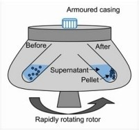
The equilibrium between the two forces, together with the size and density of the particles in the solution, determines the extension of particle migration, in such a way that it is dependent on the tube position in the centrifuge’s rotor (Figure 1).

centrifuge rotor and sample positioning

Figure 1: Schematic representation of a centrifuge rotor and sample positioning before and after centrifugation (image credit: fisherscientific).

Different centrifuges are available on the market, specifically designed for certain applications. In general, centrifuges are sold with a range of accessories, that can be used depending on the goal of a particular centrifugation protocol.

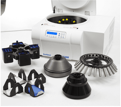
The centrifuge rotor is an essential element of the device, which determines not only the sample size but also how the particles migrate and distribute in solution after centrifugation. Some centrifuges come with more than one rotor, widening the scope of their applications (Figure 2). Older centrifuges, however, are sold with only one undetachable rotor (Biocompare, 2019).

In this article, you will learn about the different centrifuge rotors, how to choose between the myriad of market offers, and how to properly maintain them, to assure a functional, accurate, and long-lived centrifuge in your laboratory.

A multipurpose high-speed refrigerated centrifuge

Figure 2: A multipurpose high-speed refrigerated centrifuge with a wide range of rotors, buckets, and adaptors (image credit: Labogene)

Rotor Types

Depending on the application, the centrifugal forces generated in laboratory centrifuges can vary from a few hundred g up to 1 000 000 × g (Biocompare, 2019).

Accordingly, centrifuge rotors are made from different materials.  Low-speed rotors are usually made of steel or brass, while high-speed rotors consist of aluminum, titanium, or fiber-reinforced composites. The exterior of specific rotors might be finished with protective paints.

For example, rotors for ultracentrifugation made out of titanium alloy are covered with a polyurethane layer and aluminum rotors are protected from corrosion by a tough, electrochemically formed layer of aluminum oxide (Table 1) (Ohlendieck & Harding, 2017).

Table 1: Comparison of rotor materials

Aluminum Titanium Carbon Fiber
Highly susceptible to acid, alkali, or salt corrosion
Moderately susceptible to acid, alkali, or salt corrosion
(1) Corrosion-free (2) No deration due to high strength to weight ratio of rotor materials
Anodizing may lead to stress corrosion
May require deration due to repeated run cycles
(1) No stretching or elongation during centrifugation (2) Lightweight
Heavy material; uses increased energy to spin
(1) Heat insulating maintains sample temperature (2) Environmentally-friendly production process

Griffith O.M., in Practical Techniques for Centrifugal Separations, by ThermoFischer)

For a wide range of routine applications, the standard benchtop and clinical centrifuges may present one of the following types of rotors (Ohlendieck & Harding, 2017):

Multiple Container Rotors

1. Swinging-bucket rotors

Available for purchase here. During centrifugation, the rotor buckets swing out in the same direction of the centrifugal force, elevating the sample up to 90º relative to the rotation axis (Figure 3).

This type of rotor is mainly used for rate zonal centrifugation, i.e., to separate particles as a function of their size and density, in which the maximum resolution in particle separation is needed (Ohlendieck, 2017).

Swinging-bucket rotors are also suitable for isopycnic centrifugation, i.e., separation based on density only. However, to attain maximum particle separation, the centrifugation process may be too time-consuming. 

Given that during centrifugation, tubes reach a 90ºC angle, the overall particle migration distance is higher than in fixed-angle rotors. As particles with small sizes migrate to the complete extension of the sample tube, the time to reach the tube bottom is higher than fixed-angle or vertical-tube rotors.

Advantages: Higher separation resolution; adaptable to different sample containers and volumes (e.g., plates, 15mL tubes, 50 mL tubes and bottles)

Disadvantages: Longer centrifugation times; lower number of tubes per run than fixed-angle rotors

swinging bucket rotor

Figure 3: (A) example of a swinging-bucket rotor (image credit: Beckman Coulter Life Sciences); (B) Schematic representation of the centrifugal field and particle movement in swinging-bucket rotors (image credit: microbionotes).

2. Fixed-angle rotors

Available for purchase here. Tubes are held in a fixed position (usually 45º) relative to the rotational axis. Because of that, particles migrate in a downward spiral manner, and sediment in the bottom of the tube. Smaller rotor angles result in more diffuse sediment (pellet). 

Fixed-angle rotors are suitable for the fractionation of samples in which the sedimentation rates of the different components differ significantly, such as the separation of cellular components like mitochondria, cell nuclei, and cytoplasmic content (Ohlendieck & Harding, 2017).

Advantages:

  • Fixed-angle rotors usually accommodate a higher number of samples than swing-bucket rotors, which makes them more suitable for high throughput applications;
  • Because of the rigid design of the metal alloy material, fixed rotors can resist much higher gravitational forces, with minimum metal stress, which are used for the separation of biological macromolecules such as RNA, DNA, and protein.

Disadvantages:

  • Fixed vessel capacity;
  • Impossible to adapt different sample containers than the ones provided by the rotor by default.
fixed angle rotor

Figure 3: (A) example of a fixed-angle rotor (image credit: Beckman Coulter Life Sciences); (B) Schematic representation of the centrifugal field and particle movement in swinging-bucket rotors (image credit: microbionotes).

3. Vertical rotors and near-vertical rotors

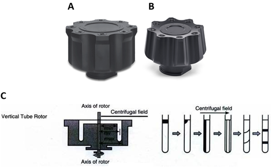
Tubes are held between 0º – 9º from the axis of rotation, which represents the shortest radial distance, and therefore the shortest pathlength for particles during centrifugation. In vertical and near-vertical rotors, particles sediment throughout the wall of the tube. Due to the shorter radial distance, centrifugation time is reduced, which may be important for certain biological samples.

However, the particle separation resolution is significantly reduced: during centrifugation, particles sediment through the tube wall, however, when the rotor deaccelerates and stops, the sedimented particles fall off the tube wall and contaminate the separated sample zones (Griffith, 2010; Ohlendieck & Harding, 2017).

Advantages: Shorter run times.

Disadvantages: Low particle separation resolution.

vertical rotor

Figure 3: (A) example of a vertical rotor; (B) example of a near-vertical rotor (image credit: Beckman Coulter Life Sciences); C. Schematic representation of the centrifugal field and particle movement in swinging-bucket rotors (image credit: microbionotes).

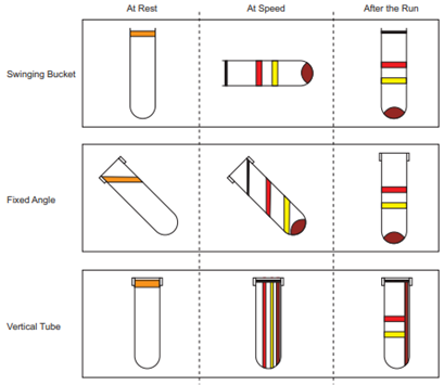
Sample orientation in Swinging-bucket, fixed-angle and vertical-tube rotors

Figure 4: Sample orientation in Swinging-bucket, fixed-angle, and vertical-tube rotors (image credit: Griffith O.M., in Practical Techniques for Centrifugal Separations, by ThermoFischer)

Continuous Flow (“hollow”) Rotors

1. Continuous-flow rotors

They are used to process large volumes of samples with high centrifugal forces, in a less time-consuming manner, as their use avoids start-and-stop to consecutively decant the supernatant. This type of rotor is used to recover large volumes of biological components such as viruses, mitochondria, bacteria, and algae.

Advantages:

  • Reduced centrifugation time due to short radial distance, and hence, short pathlength;
  • The sample is loaded in a stream on the rotor, which facilitates the flow of the material;
  • A large volume of samples is allowed, which also contributes to the reduced centrifugation time.

Disadvantages:

  • Long accelerating/de-accelerating times. This may be problematic when the sample stream is highly enriched in the solid component, which makes the rotor “over-efficient”. This means that when there is too much solid component in the sample, the rotor fills up too quickly. This requires the rotor to be stopped to unload the pellet, and then to be restarted to resume the centrifugation of the rest of the sample. Therefore, when using continuous-flow centrifugation, the solid/liquid ratio must be kept between 5 – 15% (Beckman Coulter);
  • Does not allow gradient centrifugation;
  • Equipment cost – highly expensive.

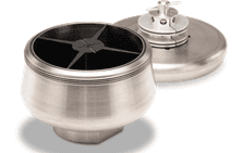
2. Zonal rotors

They are similar to continuous flow rotors but suitable for differential centrifugation, as they allow for density gradient solutions to be loaded prior to the target solution (Plüisch, Bössenecker, Doblera, & Wittemann, 2019; Spragg, 1978).  

Zonal rotors are used for large-scale zonal centrifugation, recovering the sample components as bands in a gradient.

Advantages:

  • Sample loading and recovery without the need to stop the rotor, significantly decreasing the centrifugation time compared to continuous-flow rotors;
  • Suitable for differential (rate-zonal and isopycnic) centrifugation and sample fractionation.

Disadvantages:

  • The gradient tends to swirl as it reorients when the rotor is stopped;
  • Equipment cost – highly expensive
zonal rotor
A
Zonal rotor centrifugation
B

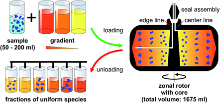
Figure 4 (A) Example of a zonal rotor (image credit: Beckman Coulter Life Sciences); (B) Zonal rotor centrifugation: a density gradient is introduced at the edge of a hollow rotor, while it is spinning at reduced speed. Loading starts with the lightest portion of the gradient first, followed by layers of increasing densities.

Once the gradient fills the rotor completely, the sample suspension is introduced at the rotor core as the last material loaded. Separation is accomplished by sorting the particles according to their sedimentation coefficients.

At the end of the centrifuge run, the rotor speed is reduced and its content is displaced out through the center exit by pumping a sufficiently dense solution into the edge line. Suspensions of sorted nanoparticles can be picked up using a fraction collector system (Plüisch et al., 2019).

3. Airfuge rotors

They are specially designed for pelleting small particles such as viruses and proteins. The rotor is supplied and driven by a pressurized air source. Rotor speed can be determined by the conversion of the applied air pressure to rotations per minute (rpm). 

Importantly, the deceleration process is very slow to avoid a mixture of the sample components. Airfuge rotors are held in place by a pressure differential created by the applied centrifugation force, which makes these rotors extremely safe. Furthermore, in Airfuge centrifuges, a filter is supplied with the ultracentrifuge for water and oil removal from the air supply.

Advantages:

  • Suitable for the separation of extremely small particles, such as cell components and virus
  • Increased safety when compared to all other centrifuge types, due to the pressure differential that is generated by the air source.

Disadvantages:

  • Limited vessel capacity and limited sample volume (up to a few milliliters)

Special Maintenance:

  • The filter must be replaced regularly.

4. Analytical Ultracentrifuge (AUC) Rotors

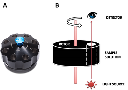
Analytical ultracentrifugation combines high-speed centrifugation with optical detection systems to observe particle separation in real-time. Therefore, AUC rotors must allow light to reach the sample.

Advantages:

  • Possibility to follow particle separation and to acquire data (such as sedimentation rate, particle size, etc.) in real-time

Disadvantages:

  • Limited vessel capacity and limited sample volume
  • Equipment cost – highly expensive
analytical ultracentrifugation rotor

Figure 5: (A). Example of an analytical ultracentrifugation rotor (image credit: Beckman Coulter Life Sciences); (B). Schematic representation of the centrifugal field and particle movement in swinging-bucket rotors (image credit: Institute of Molecular Biophysics, Florida State University).

5. Elutriation rotors

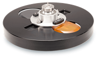
They are designed to concentrate monodisperse solutions of single cells or particles, according to their size. Elutriation rotors combine centrifugal force and fluid velocity, two forces that affect particle migration. Centrifugal force drives articles away from the rotational axis, while fluid velocity drives them in the opposite direction – counterflow elutriation (Figure 6).

Advantages:

  • Cell recovery with high viability
  • Separated cells can be used further
  • Not time-consuming

Disadvantages:

  • It does not allow for differential cell separation, i.e., cells with different properties but similar sedimentation rates will migrate to the same gradient phase. Therefore, to perform cell-type separation, previous purification processes are necessary;
  • Equipment cost – highly expensive
elutriation rotor
A
Cell separation using counter current elutriation
B

Figure 6: An example of an elutriation rotor (image credit: Beckman Coulter Life Sciences); B. Cell separation using counter-current elutriation. (A) Cells are fed into a spinning rotor, where the centrifugal force is balanced by a counter-directed buffer flow. (B) Depending on size, cells are differentially affected by the centrifugal force and separation occurs. (C) By slowly increasing the flow rate, fractions of cells of well-defined sizes can be recovered. Image credit: (Thorén, 2007).

General Guidance for the Maintenance of Centrifuge Rotors

(Goodman, 2007)

Rotor care and maintenance are essential for ensuring the safety and longevity of rotors and centrifuges. In general, the same maintenance and care principles apply to all of the rotors mentioned in this article.

  • Samples must be properly equilibrated, when loading;
  • Store in a dry place, in an inverted position to avoid moisture accumulation in the sample holes;
  • Cleaning with non-abrasive detergents;
  • Sterilization via UV light may be necessary when samples include live cells, bacteria or virus;
  • Regular maintenance by a certified technician required;
  • The operator(s) must follow the manufacturer’s manual for other specific instructions on the care and maintenance of the acquired rotor.

Final Words

The key component of centrifuges is the rotor, which determines the sample volume and the type of particle separation. Nowadays, there are, in the market, several options that allow the researcher to choose the optimal rotor, suitable for specific applications.

The main disadvantages of certain types of rotors are the limited sample capacity and, in some cases, the elevated cost. Therefore, it is important to keep appropriate care and maintenance, to ensure a proper long-lived functional device.

References

  1. (2019). Laboratory Centrifuges. Retrieved November, 2019, from https://www.biocompare.com/Lab-Equipment/Laboratory-Centrifuges/
  2. Coulter, B. Continuous Flow Rotors. 2020, from https://beckman.com/centrifuges/rotors/continuous-flow
  3. Goodman, T. (2007). Centrifuge Rotor Selection and Maintenance. American Laboratory.
  4. Griffith, O. M. (2010). Practical Techniques for Centrifugal Separations – Application Guide.
  5. Ohlendieck, K., & Harding, S. E. (2017). Centrifugation and Ultracentrifugation.
  6. Plüisch, C. S., Bössenecker, B., Doblera, L., & Wittemann, A. (2019). Zonal rotor centrifugation revisited: new horizons in sorting nanoparticles. RSC Advances(47).
  7. Spragg, S. P. (1978). Centrifugal Separations in Molecular and Cell Biology. London: Butterworths.
  8. Thorén, F. B. (2007). Oxidant-induced cell death in lymphocytes – mechanisms of induction and resistance. (Doctoral Thesis), Goteborg University, Institute of Biomedicine, Department of Infectious Medicine.