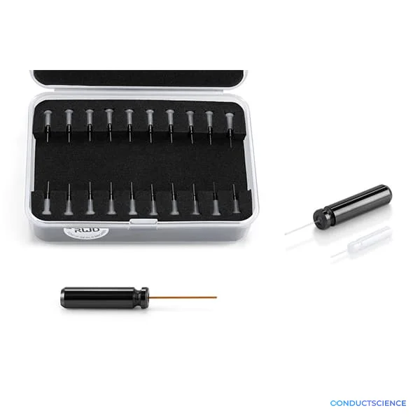
Fiber Stripper (Tongs)
: 9, 19-20/F, Building 7A, 9F Building 7D,.
| fiber_diameter_compatibility | 100um - 600um (suitable for up to 800um for stripping fiber coating) |
| handle_design | Ergonomic handle design, comfortable grip |
| cutting_surface_feature | All cutting surfaces have precision mechanical tolerances |
| operation_quality | Clean, smooth operation |
| fiber_protection | Prevents damage to the fiber |
| Automation Level | manual |
Fiber Stripper - suitable for 100um - 600um fiber
- Suitable for 100um-800um for stripping fiber coating.
- Prevents damage to the fiber.
- All cutting surfaces have precision mechanical tolerances to ensure clean, smooth operation.
- Ergonomic handle design, comfortable grip.
Specifications
| Cat No. | Description |
|---|---|
| R-FC-P-N2-100-L1 | Optic Fiber(m), FC/PC Adapter with Ø2.5 mm Ceramic Ferrule, 100um Core,0.22NA,1m |
| R-FC-P-N2-200-L1 | Optic Fiber(m), FC/PC Adapter with Ø2.5 mm Ceramic Ferrule, 200um Core,0.22NA,1m |
| R-FC-P-N2-300-L1 | Optic Fiber(m), FC/PC Adapter with Ø2.5 mm Ceramic Ferrule, 300um Core,0.22NA,1m |
| R-FC-P-N2-400-L1 | Optic Fiber(m), FC/PC Adapter with Ø2.5 mm Ceramic Ferrule, 400um Core,0.22NA,1m |
| R-FC-L-N2-100-L1 | Optic Fiber(m), FC/PC Adapter with Ø1.25 mm Ceramic Ferrule, 100um Core,0.22NA,1m |
| R-FC-L-N2-200-L1 | Optic Fiber(m), FC/PC Adapter with Ø1.25 mm Ceramic Ferrule, 200um Core,0.22NA,1m |
| R-FC-L-N2-300-L1 | Optic Fiber(m), FC/PC Adapter with Ø1.25 mm Ceramic Ferrule, 300um Core,0.22NA,1m |
| R-FC-L-N2-400-L1 | Optic Fiber(m), FC/PC Adapter with Ø1.25 mm Ceramic Ferrule, 400um Core,0.22NA,1m |
| R-FC-P-N3-200-L1 | Optic Fiber(m), FC/PC Adapter with Ø2.5 mm Ceramic Ferrule, 200um Core,0.39NA,1m |
| R-FC-P-N3-300-L1 | Optic Fiber(m), FC/PC Adapter with Ø2.5 mm Ceramic Ferrule, 300um Core,0.39NA,1m |
| R-FC-P-N3-400-L1 | Optic Fiber(m), FC/PC Adapter with Ø2.5 mm Ceramic Ferrule, 400um Core,0.39NA,1m |
| R-FC-L-N3-200-L1 | Optic Fiber(m), FC/PC Adapter with Ø1.25 mm Ceramic Ferrule, 200um Core,0.39NA,1m |
| R-FC-L-N3-300-L1 | Optic Fiber(m), FC/PC Adapter with Ø1.25 mm Ceramic Ferrule, 300um Core,0.39NA,1m |
| R-FC-L-N3-400-L1 | Optic Fiber(m), FC/PC Adapter with Ø1.25 mm Ceramic Ferrule, 400um Core,0.39NA,1m |
How It Works
The fiber stripper operates through controlled mechanical abrasion of the polymer coating surrounding the optical fiber core and cladding. The precision-machined cutting surfaces create controlled contact pressure that selectively removes the protective coating without damaging the underlying glass fiber structure. The mechanical tolerances of the cutting edges are designed to accommodate the specific hardness differential between polymer coatings and silica glass.
The tong mechanism provides leverage multiplication, allowing controlled force application during the stripping process. As the fiber is drawn through the closed cutting surfaces, the polymer coating is mechanically abraded away, exposing the clean glass surface required for optical coupling. The ergonomic handle design enables precise control over stripping force and fiber positioning to prevent core damage or surface scratching that would degrade optical transmission properties.
Features & Benefits
fiber_diameter_compatibility
- 100um - 600um (suitable for up to 800um for stripping fiber coating)
handle_design
- Ergonomic handle design, comfortable grip
cutting_surface_feature
- All cutting surfaces have precision mechanical tolerances
operation_quality
- Clean, smooth operation
fiber_protection
- Prevents damage to the fiber
Automation Level
- manual
Brand
- RWD
Research Domain
- Analytical Chemistry
- Behavioral Pharmacology
- Cell Biology
- Materials Science
- Neuroscience
Weight
- 8.27 lbs
Dimensions
- L: 34.0 in
- W: 39.0 in
- H: 33.0 in
Comparison Guide
| Feature | This Product | Typical Alternative | Advantage |
|---|---|---|---|
| Fiber Diameter Range | 100-600µm (up to 800µm for coating removal) | Entry-level models often limited to narrower diameter ranges | Accommodates diverse fiber types used across research applications without requiring multiple tools. |
| Cutting Surface Precision | Precision mechanical tolerances on all cutting surfaces | Basic models may lack precision tolerances | Ensures consistent coating removal without fiber damage that degrades optical performance. |
| Handle Design | Ergonomic tong design with comfortable grip | Basic tools often have simple handle designs | Provides better control and reduces hand fatigue during extended fiber preparation sessions. |
| Operation Quality | Clean, smooth operation mechanism | Lower-cost alternatives may have rougher operation | Enables consistent results across multiple fibers, improving connector preparation reliability. |
This fiber stripper combines broad diameter compatibility with precision mechanical design for reliable coating removal in research applications. The ergonomic tong design provides controlled operation for consistent results across diverse fiber preparation requirements.
Practical Tips
Test stripping force on sample fiber before processing critical specimens to establish optimal pressure settings.
Why: Different coating materials may require adjusted force to prevent fiber damage while ensuring complete removal.
Clean cutting surfaces with appropriate solvents after each use session to remove coating residue buildup.
Why: Accumulated residue can cause uneven stripping and potential fiber surface contamination.
Maintain steady, continuous motion when drawing fiber through closed cutting surfaces rather than jerky movements.
Why: Smooth motion prevents surface scratching and ensures uniform coating removal along the stripped length.
If coating removal is incomplete, verify fiber diameter compatibility and check for cutting surface wear or debris.
Why: Worn or contaminated cutting edges lose effectiveness and may require cleaning or tool replacement.
Inspect stripped fiber ends under magnification before connector installation to verify clean coating removal.
Why: Residual coating material can interfere with proper connector seating and degrade optical coupling efficiency.
Handle stripped fiber sections carefully to avoid contact with skin, as glass particles may be present.
Why: Glass fragments from the stripping process can cause skin irritation or embed in tissue.
Position stripping location to provide adequate length for connector requirements while minimizing exposed fiber handling.
Why: Optimal stripping length balances connector assembly needs with protection of the fragile exposed glass section.
Setup Guide
What’s in the Box
- Fiber stripper tool (typical)
- User instruction sheet (typical)
Warranty
ConductScience provides standard manufacturer warranty coverage with technical support for proper tool operation and maintenance procedures.
Compliance
References
Background reading relevant to this product:
What fiber diameters are compatible with this stripper?
The tool is designed for 100-600µm core diameter fibers, with extended compatibility up to 800µm specifically for coating stripping operations.
How do I prevent fiber damage during stripping?
Use controlled pressure when closing the tong mechanism and maintain smooth, continuous motion when drawing the fiber through the cutting surfaces to avoid surface scratching.
What maintenance is required for the cutting surfaces?
Regular cleaning to remove coating residue and periodic inspection for edge damage that could scratch fibers during stripping operations.
Can this tool strip both single-mode and multimode fibers?
Yes, the diameter compatibility range covers both single-mode and multimode fibers commonly used in research applications.
What stripping length can be achieved?
Stripping length is controlled by user technique and fiber positioning, typically 10-15mm for standard connector preparation requirements.
How does this compare to thermal stripping methods?
Mechanical stripping provides immediate results without heating requirements, though thermal methods may offer cleaner removal for some coating types.