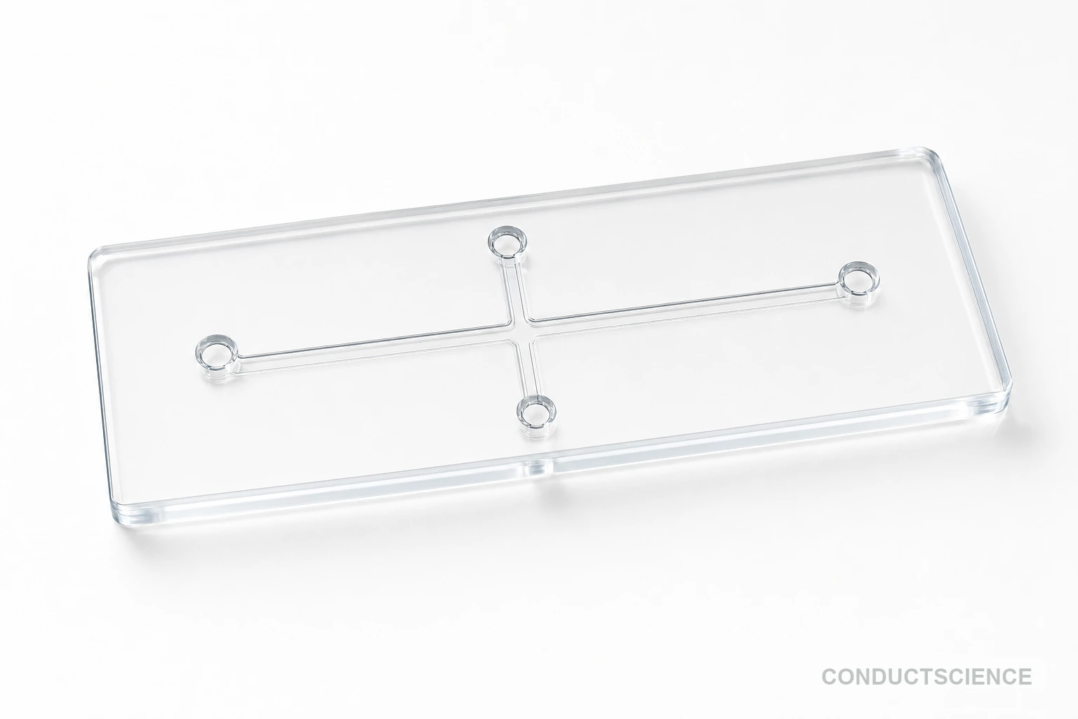
Cross-Junction Droplet Generator Chip
Microfluidic cross-junction chip with 100 μm channel depth for controlled droplet generation and emulsion formation in research applications.
Reusable chip — designed for multiple experimental runs. Compatible with standard microfluidic tubing: steel pins (0.7 mm ID / 1.0 mm OD) and silicone tubing (0.8 mm ID / 1.9 mm OD). Available in bulk packs (5‑, 10‑, and 25‑unit) for lab-scale and consumable workflows.

Louise Corscadden, PhD
Director of Science · ConductScience
Ask Louise about Cross-Junction Droplet Generator Chip fit, setup, configuration, or quote prep.
Already working with us? Sign in to connect this with My Scientist.
Key Specifications
Full details →- Model fit
- 3 selectable configurations
- SKU family
- WHM-0020
- Sizing
- 25.0 x 15.0 x 3.0 cm
- Ordering
- Online checkout and quote request available
- Category
- Lab Equipment
- Build notes
- Confirm accessories, station layout, and support needs before purchase
The Cross-Junction Droplet Generator Chip is a microfluidic device designed for precise droplet formation in emulsion-based research applications. Featuring a cross-junction geometry with 100 μm channel depth, this chip enables controlled generation of monodisperse droplets through the intersection of continuous and dispersed phase flows. The device operates on the principle of flow-focusing, where shear forces at the junction create consistent droplet breakup for reproducible emulsion production.
Fabricated with standard microfabrication techniques, the chip provides researchers with a reliable platform for droplet microfluidics experiments. The 25 mm x 15 mm x 3 mm form factor offers compatibility with standard microscopy setups and microfluidic accessories. Applications span from fundamental studies of droplet formation mechanics to development of encapsulation protocols for biological samples and chemical synthesis.
Key Specs
| Material | PDMS |
|---|---|
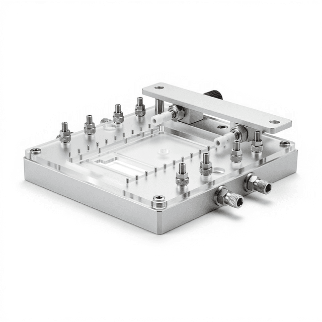
| Geometry | Cross/plus junction, 4 ports |
| Ports | 4 ports (Port 1, Port 2, Port 3, Port 4) |
| Chip footprint | 25.4 x 76.2 mm standard slide format |
| Channel width | 50 um, 100 um, 150 um, 200 um |
| Channel depth | 50 um |
| Bonding | PDMS-PDMS, PDMS-glass |
| Packaging | Standard glass slide (25.4x76.2mm), stainless steel tubes (0.7x1.0x15mm), silicone tubing (0.8x1.9mm) |
| Source | suppliers/wenhao/docs/pdms-chips-catalog.json; 3.2.002.00.009, 3.2.002.00.010, 3.2.002.00.011, 3.2.002.00.012, 3.2.002.00.013, 3.2.002.00.014, 3.2.002.00.015, 3.2.002.00.016 |
This source-backed block lists available source configurations; confirm selected width/bonding when quoting.
How It Works
The cross-junction droplet generator operates through hydrodynamic flow focusing at the intersection of perpendicular microchannels. The continuous phase fluid flows through the main channel while the dispersed phase is introduced through the perpendicular inlet. At the junction, shear forces from the continuous phase overcome the surface tension of the dispersed phase, causing periodic pinch-off and droplet formation.
Droplet size is controlled by the flow rate ratio between continuous and dispersed phases, fluid viscosities, and channel geometry. The 100 μm channel depth provides sufficient volume for droplet formation while maintaining laminar flow conditions. The cross-junction design ensures consistent droplet breakup through symmetric shear application, resulting in coefficient of variation typically below 5% for monodisperse emulsions.
Surface wetting properties of the channel walls determine the wetting regime and droplet formation mechanism. Hydrophobic surface treatments favor water-in-oil emulsions, while hydrophilic surfaces support oil-in-water systems. The chip design accommodates various fluid combinations through appropriate surface functionalization protocols.
Features & Benefits
Channel Width
- 100 um
- 150 um
- 200 um
- 50 um
Bonding Type
- PDMS-Glass
- PDMS-PDMS
Pack Size
- 5-Pack
- 10-Pack
- 25-Pack
Weight
- 0.03 kg
Dimensions
- L: 25.0 mm
- W: 15.0 mm
- H: 3.0 mm
| Feature | This Product | Typical Alternative | Advantage |
|---|---|---|---|
| Channel Pattern | Cross junction (十型) — 4 ports at perpendicular intersection | Four-way flow control for droplet generation and multi-stream experiments | |
| Channel Depth | 50 μm (fixed) | Standard across all configurations in this product line | |
| Channel Width Options | 50, 100, 150, or 200 μm (8 configurations total) | Wider channels reduce clogging risk; narrower channels produce smaller droplets | |
| Bonding Options | PDMS-to-PDMS or PDMS-to-glass | Glass bonding recommended for optical monitoring of droplet formation | |
| Manufacturer Part Numbers | 3.2.002.00.009 through 3.2.002.00.016 (Model: WHBZ-CC) | Odd numbers = PDMS-PDMS; even numbers = PDMS-glass | |
| Chip Dimensions | 25 × 15 × 3 mm chip on 25.4 × 76.2 mm glass slide | Standard microscope slide format | |
| Included Accessories | Stainless steel tubes (0.7 × 1.0 × 15 mm), silicone tubing (0.8 × 1.9 mm) | 4 connection points; connect each to independent syringe pump or reservoir |
Cross-junction PDMS chip for multi-stream intersection, droplet generation, and flow-switching experiments. 4-port design enables co-flow and flow-focusing configurations. 8 configurations: 4 widths × 2 bonding types.
| Model | SKU | Listed price | Status | Dimensions |
|---|---|---|---|---|
| 25-Pack | WHM-0020-200-um-pdms-glass-25-pack | Quote | Available | 25.0 x 15.0 x 3.0 cm |
| 10-Pack | WHM-0020-200-um-pdms-glass-10-pack | Quote | Available | 25.0 x 15.0 x 3.0 cm |
| 5-Pack | WHM-0020-200-um-pdms-glass-5-pack | Quote | Available | 25.0 x 15.0 x 3.0 cm |
| 25-Pack | WHM-0020-200-um-pdms-pdms-25-pack | Quote | Available | 25.0 x 15.0 x 3.0 cm |
| 10-Pack | WHM-0020-200-um-pdms-pdms-10-pack | Quote | Available | 25.0 x 15.0 x 3.0 cm |
| 5-Pack | WHM-0020-200-um-pdms-pdms-5-pack | Quote | Available | 25.0 x 15.0 x 3.0 cm |
| 25-Pack | WHM-0020-150-um-pdms-glass-25-pack | Quote | Available | 25.0 x 15.0 x 3.0 cm |
| 10-Pack | WHM-0020-150-um-pdms-glass-10-pack | Quote | Available | 25.0 x 15.0 x 3.0 cm |
| 5-Pack | WHM-0020-150-um-pdms-glass-5-pack | Quote | Available | 25.0 x 15.0 x 3.0 cm |
| 25-Pack | WHM-0020-150-um-pdms-pdms-25-pack | Quote | Available | 25.0 x 15.0 x 3.0 cm |
| 10-Pack | WHM-0020-150-um-pdms-pdms-10-pack | Quote | Available | 25.0 x 15.0 x 3.0 cm |
| 5-Pack | WHM-0020-150-um-pdms-pdms-5-pack | Quote | Available | 25.0 x 15.0 x 3.0 cm |
| 25-Pack | WHM-0020-100-um-pdms-glass-25-pack | Quote | Available | 25.0 x 15.0 x 3.0 cm |
| 10-Pack | WHM-0020-100-um-pdms-glass-10-pack | Quote | Available | 25.0 x 15.0 x 3.0 cm |
| 5-Pack | WHM-0020-100-um-pdms-glass-5-pack | Quote | Available | 25.0 x 15.0 x 3.0 cm |
| 25-Pack | WHM-0020-100-um-pdms-pdms-25-pack | Quote | Available | 25.0 x 15.0 x 3.0 cm |
| 10-Pack | WHM-0020-100-um-pdms-pdms-10-pack | Quote | Available | 25.0 x 15.0 x 3.0 cm |
| 5-Pack | WHM-0020-100-um-pdms-pdms-5-pack | Quote | Available | 25.0 x 15.0 x 3.0 cm |
| 25-Pack | WHM-0020-50-um-pdms-glass-25-pack | Quote | Available | 25.0 x 15.0 x 3.0 cm |
| 10-Pack | WHM-0020-50-um-pdms-glass-10-pack | Quote | Available | 25.0 x 15.0 x 3.0 cm |
| 5-Pack | WHM-0020-50-um-pdms-glass-5-pack | Quote | Available | 25.0 x 15.0 x 3.0 cm |
| 25-Pack | WHM-0020-50-um-pdms-pdms-25-pack | Quote | Available | 25.0 x 15.0 x 3.0 cm |
| 10-Pack | WHM-0020-50-um-pdms-pdms-10-pack | $1,490.00 | Available | 25.0 x 15.0 x 3.0 cm |
| 5-Pack | WHM-0020-50-um-pdms-pdms-5-pack | Quote | Available | 25.0 x 15.0 x 3.0 cm |
Practical Tips
Establish baseline flow rate ratios using known fluid pairs before introducing experimental samples.
Why: Reference conditions help identify optimal operating parameters for new fluid combinations.
Flush channels with appropriate solvents immediately after each experiment to prevent residue buildup.
Why: Residual materials can alter surface properties and affect subsequent droplet formation consistency.
Filter all fluids through 0.22 μm filters before use to remove particles that could block channels.
Why: Particulate contamination can disrupt flow patterns and cause irregular droplet formation.
If droplet formation becomes irregular, check for air bubbles in inlet tubing and re-prime channels.
Why: Air bubbles disrupt the pressure balance needed for stable droplet breakup at the junction.
Allow 5-10 minutes of stable operation before collecting experimental data to ensure steady-state conditions.
Why: Initial flow establishment may show transient behavior that doesn't represent true device performance.
Use appropriate chemical compatibility guidelines when selecting fluids and ensure proper ventilation for organic solvents.
Why: Device materials and surface treatments may not be compatible with all chemical systems.
Document flow rate settings and fluid properties for each successful experiment to enable reproducibility.
Why: Droplet formation is sensitive to multiple parameters that must be carefully controlled across experiments.
Store chip in clean, dry conditions and inspect channels before each use to verify clarity.
Why: Contamination or moisture can compromise surface treatments and alter wetting behavior.
Setup Guide
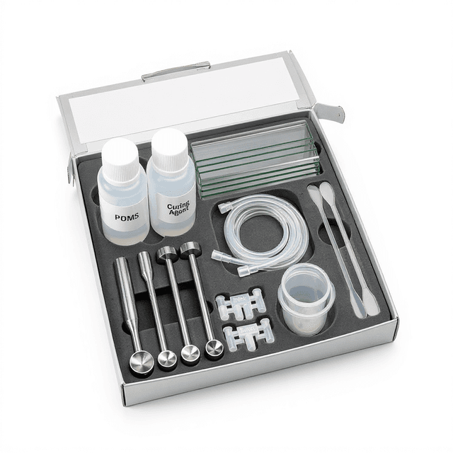
What’s in the Box
- Cross-Junction Droplet Generator Chip
- User manual with operation protocols (typical)
- Quality control certificate (typical)
Warranty
ConductScience provides a one-year manufacturer warranty covering defects in materials and workmanship. Technical support includes application guidance and troubleshooting assistance for optimal device performance.
Compliance
What flow rate ranges work best with this chip geometry?
Optimal performance typically occurs with continuous phase flow rates of 10-100 μL/min and dispersed phase rates of 1-10 μL/min. The 100 μm channel depth accommodates these ranges while maintaining laminar flow conditions necessary for stable droplet formation.
How do I achieve consistent droplet sizes?
Maintain constant flow rate ratios using precision syringe pumps, ensure complete channel priming to eliminate air bubbles, and use fluids with appropriate viscosity ratios. Temperature control also helps maintain fluid property consistency.
What surface treatments are compatible with this chip?
Standard silanization protocols work for hydrophobic treatments, while plasma treatment or hydrophilic coatings enable aqueous-continuous emulsions. Consult product datasheet for specific coating compatibility and application procedures.
Can this chip handle viscous fluids?
The 100 μm channel depth accommodates moderately viscous fluids, but higher viscosities may require adjusted flow rates or heating to maintain proper droplet formation. Pressure limitations depend on your pump system specifications.
How long do the channels remain stable during operation?
With proper surface treatment and compatible fluids, channels typically maintain stable droplet production for several hours of continuous operation. Performance duration depends on fluid properties and potential fouling or wetting changes.
What microscopy requirements are needed for observation?
Standard brightfield or fluorescence microscopy with 10x-40x objectives works well given the 3 mm chip thickness. High-speed imaging capabilities are recommended for detailed droplet formation dynamics studies.
How does this compare to T-junction designs?
Cross-junction geometry provides more symmetric shear forces compared to T-junctions, often resulting in better droplet size uniformity. The trade-off is slightly more complex flow dynamics but improved control over droplet formation mechanisms.
Have a question about this product?
Have a question? Just ask.
Send it over and we'll email you a personalized answer — no call, no scheduling.
Prefer to talk it through?