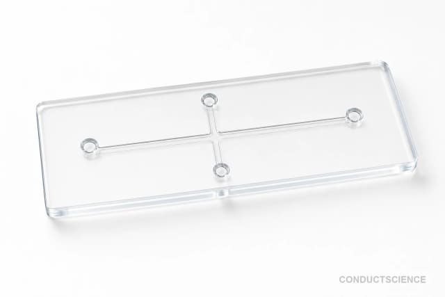
PDMS Large-Channel Droplet Generator Chip
Cross-junction PDMS microfluidic chip with 400 μm channel depth for controlled generation of large droplets in research applications.
Reusable chip — designed for multiple experimental runs. Compatible with standard microfluidic tubing: steel pins (0.7 mm ID / 1.0 mm OD) and silicone tubing (0.8 mm ID / 1.9 mm OD). Available in bulk packs (5‑, 10‑, and 25‑unit) for lab-scale and consumable workflows.

Louise Corscadden, PhD
Director of Science · ConductScience
Ask Louise about PDMS Large-Channel Droplet Generator Chip fit, setup, configuration, or quote prep.
Already working with us? Sign in to connect this with My Scientist.
Key Specifications
Full details →- Model fit
- 3 selectable configurations
- SKU family
- WHM-0021
- Sizing
- 25.0 x 15.0 x 3.0 cm
- Ordering
- Online checkout and quote request available
- Category
- Lab Equipment
- Build notes
- Confirm accessories, station layout, and support needs before purchase
The PDMS Large-Channel Droplet Generator Chip is a cross-junction microfluidic device engineered for controlled droplet formation in applications requiring larger droplet sizes. Fabricated from polydimethylsiloxane (PDMS), this chip features 400 μm channel depth specifically designed to accommodate viscous fluids and generate droplets in the larger size range compared to standard microfluidic devices.
The cross-junction geometry provides stable droplet formation through controlled flow focusing of two immiscible phases. The 400 μm channel depth allows for higher flow rates and accommodates applications where larger droplet volumes are required for encapsulation, reaction vessels, or templating applications. This chip dimension enables processing of samples that would be difficult to handle in smaller channel geometries.
How It Works
The droplet generator operates on the principle of flow focusing at a cross-junction geometry. Two immiscible fluid phases - typically an aqueous dispersed phase and an oil continuous phase - are introduced through separate inlets. The dispersed phase flows through the central channel while the continuous phase flows through perpendicular channels, creating a focused flow regime at the junction.
Droplet formation occurs through the Rayleigh-Plateau instability when the dispersed phase stream is pinched off by the shear forces from the continuous phase. The cross-junction design provides stable droplet formation with good size control through adjustment of flow rate ratios between the phases. The 400 μm channel depth allows for processing of more viscous fluids and generation of larger droplets compared to shallow-channel devices.
The PDMS material provides optical transparency for real-time monitoring of droplet formation and allows for surface modification through plasma treatment or silanization when specific wetting properties are required for particular applications.
Features & Benefits
Pack Size
- 5-Pack
- 10-Pack
- 25-Pack
Weight
- 0.02 kg
Dimensions
- L: 25.0 mm
- W: 15.0 mm
- H: 3.0 mm
| Feature | This Product | Typical Alternative | Advantage |
|---|---|---|---|
| Channel Depth | 400 μm depth | Standard chips often use 50-100 μm depths | Enables processing of viscous samples and larger droplet generation |
| Junction Design | Cross-junction geometry | T-junction configurations are common | Provides more stable flow focusing for consistent droplet formation |
| Material | PDMS construction | Glass or thermoplastic alternatives available | Offers optical transparency with lower cost and easier fabrication |
| Chip Size | 25mm × 15mm format | Sizes vary by manufacturer | Compact footprint suitable for standard microscope stages |
| Application Focus | Large droplet generation | Many chips target small droplet formation | Optimized for applications requiring larger reaction volumes |
This chip is specifically designed for large droplet generation with its 400 μm channel depth, distinguishing it from standard shallow-channel devices. The cross-junction geometry and PDMS construction provide a reliable platform for applications requiring controlled formation of larger droplets.
| Model | SKU | Listed price | Status | Dimensions |
|---|---|---|---|---|
| 25-Pack | WHM-0021-25PK | Quote | Available | 25.0 x 15.0 x 3.0 cm |
| 10-Pack | WHM-0021-10PK | $1,490.00 | Available | 25.0 x 15.0 x 3.0 cm |
| 5-Pack | WHM-0021-5PK | Quote | Available | 25.0 x 15.0 x 3.0 cm |
Practical Tips
Prime all fluidic lines thoroughly before starting droplet generation to ensure stable flow conditions.
Why: Air bubbles cause flow instabilities that disrupt consistent droplet formation.
Inspect channel surfaces regularly under microscope for signs of fouling or damage.
Why: Channel integrity directly affects droplet formation consistency and chip lifetime.
If droplets become irregular, check for pressure fluctuations in the continuous phase line.
Why: Pressure variations are the most common cause of droplet size inconsistency.
Record flow rates, fluid properties, and environmental conditions for each experiment.
Why: Reproducible droplet generation requires consistent experimental parameters.
Use appropriate chemical compatibility guidelines when selecting solvents for cleaning or operation.
Why: PDMS can swell in certain organic solvents, affecting channel dimensions.
Calibrate droplet size measurements using particles of known diameter under the same imaging conditions.
Why: Optical measurements require calibration standards for accurate size determination.
Start with well-characterized fluid pairs before attempting complex formulations.
Why: Successful operation requires understanding of fundamental droplet formation principles.
Store chips in clean containers with minimal solvent exposure when not in use.
Why: Proper storage prevents contamination and extends chip usable lifetime.
Setup Guide
What’s in the Box
- PDMS Large-Channel Droplet Generator Chip
- Product documentation (typical)
- Handling instructions (typical)
Warranty
ConductScience provides standard warranty coverage for microfluidic devices with technical support for setup and operation guidance.
Compliance
What droplet size range can this chip generate?
Droplet size depends on flow rate ratios, fluid properties, and channel geometry. With 400 μm channel depth, typical droplet diameters range from 100-800 μm. Consult product datasheet for specific size characterization data.
What fluid viscosity range is compatible?
The 400 μm channel depth accommodates higher viscosity fluids compared to shallow channels. Compatible with aqueous solutions up to several hundred cP and most organic solvents. Specific viscosity limits depend on flow rate capabilities.
How do I optimize droplet formation?
Start with continuous phase flow rate 2-5x higher than dispersed phase. Adjust flow rate ratio to control droplet size. Monitor junction under microscope to verify stable pinch-off regime.
What surface treatments are recommended?
PDMS is naturally hydrophobic. For aqueous-continuous emulsions, plasma treatment increases surface hydrophilicity. For oil-continuous systems, untreated PDMS typically provides suitable wetting properties.
How should the chip be cleaned between uses?
Flush with solvent compatible with both phases used. For protein samples, use mild detergent followed by water rinse. Avoid harsh bases that can degrade PDMS over time.
What flow rate range is typical?
Flow rates depend on desired droplet size and fluid properties. Typical range is 1-100 μL/min for each phase. Higher rates possible with larger channel geometry compared to standard microfluidic chips.
Is the chip reusable?
Yes, PDMS chips can be reused with proper cleaning. Inspect channels for damage after each use. Replace if channels show signs of swelling, cracking, or permanent contamination.
What tubing connections are recommended?
Use tubing inner diameter smaller than channel width to avoid dead volume. PEEK or PTFE tubing with appropriate fittings provides leak-tight connections. Consult documentation for specific fitting recommendations.
Have a question about this product?
Have a question? Just ask.
Send it over and we'll email you a personalized answer — no call, no scheduling.
Prefer to talk it through?