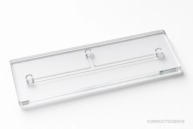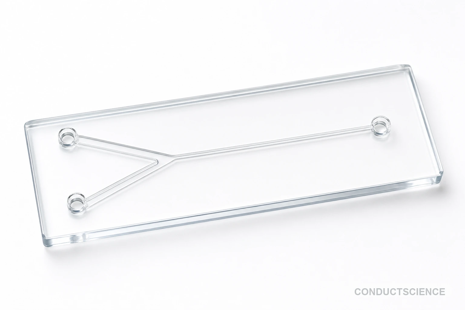
Flow-Focusing Droplet Generator Glass Chip
Precision borosilicate glass microfluidic chip for controlled droplet generation with 10-250 μm diameter range and <3% CV in both O/W and W/O emulsions.
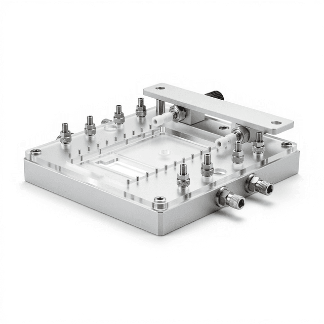
Reusable chip — designed for multiple experimental runs. Compatible with standard microfluidic tubing: steel pins (0.7 mm ID / 1.0 mm OD) and silicone tubing (0.8 mm ID / 1.9 mm OD). Available in bulk packs (5‑, 10‑, and 25‑unit) for lab-scale and consumable workflows.

Louise Corscadden, PhD
Director of Science · ConductScience
Ask Louise about Flow-Focusing Droplet Generator Glass Chip fit, setup, configuration, or quote prep.
Already working with us? Sign in to connect this with My Scientist.
Key Specifications
Full details →- Model fit
- 3 selectable configurations
- SKU family
- WHM-0002
- Sizing
- 22.5 x 15.0 x 4.0 cm
- Ordering
- Online checkout and quote request available
- Category
- Glass Chips
- Build notes
- Confirm accessories, station layout, and support needs before purchase
The Flow-Focusing Droplet Generator Glass Chip is a precision microfluidic device designed for controlled droplet formation in laboratory applications. This borosilicate glass chip utilizes flow-focusing geometry to generate monodisperse droplets with diameters ranging from 10-250 micrometers and coefficient of variation below 3%. The device features three inlet ports for continuous and dispersed phases plus one outlet port, enabling formation of both oil-in-water (O/W) and water-in-oil (W/O) emulsions.
The compact 22.5 x 15 x 4 mm chip operates across a wide temperature range (-15 to 150°C) and withstands pressures up to 10 bar, making it suitable for diverse experimental conditions. Borosilicate glass construction provides optical clarity for real-time observation, chemical inertness for compatibility with various fluids, and thermal stability for temperature-controlled experiments. This device serves as a fundamental tool for researchers requiring precise control over droplet size and production rate in microfluidic applications.
Key Specs
| Material | Borosilicate glass (glass-glass bonding) |
|---|---|
| Geometry | Flow-focusing with import/export channel widths |
| Ports | 3 ports (Sheath 1, Sheath 2, Outlet) |
| Chip footprint | 25.4 x 76.2mm standard glass slide |
| Channel width | 150 um, 250 um |
| Channel depth | 50 um, 100 um |
| Bonding | glass-glass |
| Packaging | Standard glass chip with PEEK/stainless steel connectors |
| Source | suppliers/wenhao/docs/glass-chips-catalog.json; 3.2.001.05.0018-0021 |
This source-backed block lists available source configurations; confirm selected width/bonding when quoting.
How It Works
The chip operates on flow-focusing principles where two immiscible fluids converge at a junction to form droplets. The continuous phase flows through the outer channels while the dispersed phase enters through the center inlet. At the junction, hydrodynamic forces create controlled breakup of the dispersed phase stream, forming monodisperse droplets that exit through the outlet channel.
Droplet size is controlled by adjusting the flow rate ratio between continuous and dispersed phases, with higher continuous phase flow rates producing smaller droplets. The channel geometry and surface properties of the borosilicate glass determine the droplet formation frequency and stability. Precise pressure control and flow rate management enable reproducible droplet generation with coefficient of variation below 3%.
The glass surface can be selectively modified with hydrophobic or hydrophilic treatments to optimize wetting properties for specific fluid combinations, ensuring stable droplet formation across different experimental conditions and fluid viscosities.
Features & Benefits
Pack Size
- 5-Pack
- 10-Pack
- 25-Pack
Weight
- 0.05 kg
Dimensions
- L: 22.5 mm
- W: 15.0 mm
- H: 4.0 mm
| Feature | This Product | Typical Alternative | Advantage |
|---|---|---|---|
| Droplet Size Range | 10-250 μm diameter | Entry-level devices often limited to 50-200 μm range | Extended range enables both single-cell encapsulation and larger particle synthesis applications |
| Coefficient of Variation | <3% | Standard devices typically achieve 5-10% CV | Lower variation improves experimental reproducibility and reduces data scatter in quantitative studies |
| Pressure Rating | 10 bar maximum | PDMS devices often limited to 2-5 bar | Higher pressure capability supports viscous fluids and faster production rates |
| Temperature Range | -15 to 150°C operating range | Plastic devices typically limited to room temperature to 80°C | Extended temperature range enables crystallization studies and thermally-activated reactions |
| Material Construction | Borosilicate glass | PDMS or plastic materials commonly used | Glass provides superior chemical resistance and optical clarity for solvent-based applications |
| Port Configuration | 3 inlet, 1 outlet design | Basic devices often have 2 inlet, 1 outlet | Additional inlet enables complex fluid combinations and co-flow stabilization techniques |
This glass microfluidic chip combines precision droplet formation with robust construction for demanding laboratory applications. The borosilicate glass material and 10 bar pressure rating support a broader range of experimental conditions compared to polymer-based alternatives, while the <3% CV specification ensures consistent results for quantitative studies.
| Model | SKU | Listed price | Status | Dimensions |
|---|---|---|---|---|
| 25-Pack | WHM-0002-25PK | Quote | Available | 22.5 x 15.0 x 4.0 cm |
| 10-Pack | WHM-0002-10PK | $1,490.00 | Available | 22.5 x 15.0 x 4.0 cm |
| 5-Pack | WHM-0002-5PK | Quote | Available | 22.5 x 15.0 x 4.0 cm |
Practical Tips
Calibrate droplet size measurements using known standards and verify CV calculation methods before critical experiments.
Why: Accurate size measurement is essential for reproducible results and comparison between experiments.
Store chip in protective case when not in use and inspect channels regularly under magnification for blockages or damage.
Why: Glass chips can be damaged by improper handling and channel blockages reduce performance.
Always prime continuous phase first to establish stable flow before introducing dispersed phase.
Why: Proper priming sequence prevents air bubble formation and ensures immediate stable droplet production.
If droplet formation becomes unstable, check for air bubbles in the system and verify flow rate consistency.
Why: Air bubbles and flow fluctuations are the most common causes of irregular droplet formation.
Collect at least 100 droplets for CV calculation and verify size distribution using image analysis software.
Why: Statistical validity requires adequate sample size and proper measurement techniques for meaningful results.
Use appropriate personal protective equipment when handling glass chips and ensure pressure relief systems are in place.
Why: Glass can create sharp fragments if broken and high-pressure systems require safety precautions.
Maintain consistent temperature during experiments as thermal fluctuations affect fluid viscosity and droplet size.
Why: Temperature variations can shift the operating point and compromise experimental reproducibility.
Use filtered fluids to prevent particulate contamination that can clog the narrow channel junctions.
Why: Even small particles can disrupt flow patterns and cause permanent channel damage in precision devices.
Setup Guide
What’s in the Box
- Flow-focusing droplet generator glass chip
- Protective storage case (typical)
- User manual with setup protocols (typical)
- Quality control certificate (typical)
Warranty
ConductScience provides a standard one-year manufacturer warranty covering defects in materials and workmanship. Technical support includes application guidance and troubleshooting assistance for optimal device performance.
Compliance
What factors determine the droplet size range achievable with this chip?
Droplet size is primarily controlled by the flow rate ratio between continuous and dispersed phases, with typical ranges from 10-250 μm diameter. Higher continuous phase flow rates produce smaller droplets. Fluid properties including viscosity and surface tension also influence the accessible size range.
How do I maintain the <3% coefficient of variation specification?
Stable droplet formation requires consistent flow rates, clean channels, and appropriate fluid properties. Use precision syringe pumps or pressure controllers, ensure bubble-free priming, and maintain constant temperature. Monitor the junction under magnification to verify stable breakup.
What cleaning protocols are recommended between different fluid systems?
Flush channels thoroughly with appropriate solvents compatible with both previous and next fluid systems. For biological applications, use detergent solutions followed by sterile water or buffer. For organic systems, use compatible organic solvents followed by drying.
Can this chip handle high-viscosity dispersed phases?
The 10 bar pressure rating supports moderately high-viscosity fluids, but very viscous materials may require higher pressures or heating to reduce viscosity. Consult product datasheet for specific viscosity limits and recommended operating conditions.
What microscopy setup is optimal for monitoring droplet formation?
Use an inverted microscope with at least 10x objective for junction observation. LED illumination provides stable lighting without heating effects. High-speed camera capability enables droplet formation frequency analysis and size measurement.
How do I switch between O/W and W/O emulsion formation?
Switch emulsion types by reversing the continuous and dispersed phases and potentially modifying surface wetting properties. Some applications may require surface treatment to optimize wetting characteristics for stable droplet formation.
What are the typical flow rate ranges for stable operation?
Flow rates typically range from 0.1-10 μL/min per channel depending on desired droplet size and fluid properties. Start with 2:1 continuous to dispersed phase ratio and adjust based on droplet size requirements and formation stability.
Have a question about this product?
Have a question? Just ask.
Send it over and we'll email you a personalized answer — no call, no scheduling.
Prefer to talk it through?