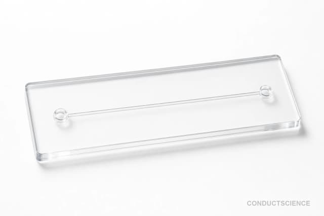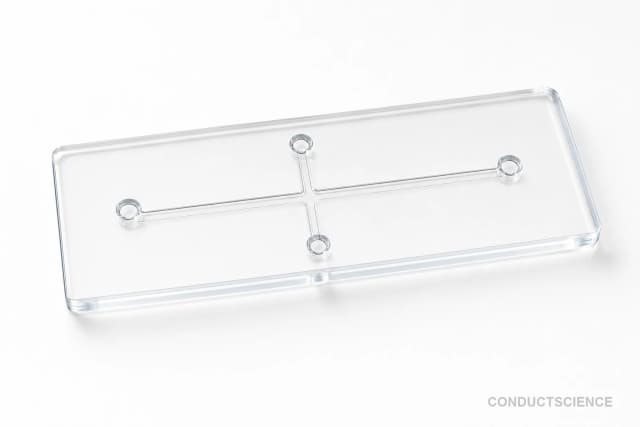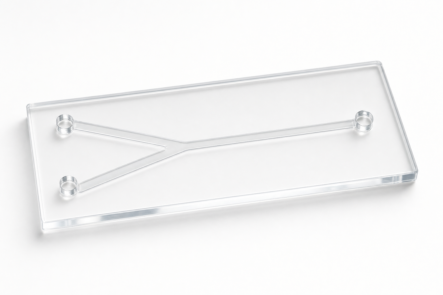
Y-Type Microfluidic Chip (300 um)
Y-junction microfluidic chip with 300 × 300 μm channels for controlled fluid mixing and laminar flow studies in lab-on-chip applications.
Reusable chip — designed for multiple experimental runs. Compatible with standard microfluidic tubing: steel pins (0.7 mm ID / 1.0 mm OD) and silicone tubing (0.8 mm ID / 1.9 mm OD). Available in bulk packs (5‑, 10‑, and 25‑unit) for lab-scale and consumable workflows.

Louise Corscadden, PhD
Director of Science · ConductScience
Ask Louise about Y-Type Microfluidic Chip (300 um) fit, setup, configuration, or quote prep.
Already working with us? Sign in to connect this with My Scientist.
Key Specifications
Full details →- Model fit
- 2 selectable configurations
- SKU family
- WHM-0114
- Sizing
- 181.8 x 136.3 x 90.9 cm
- Ordering
- Online checkout and quote request available
- Category
- Microfluidic Chips
- Build notes
- Confirm accessories, station layout, and support needs before purchase
The Y-Type Microfluidic Chip (300 μm) provides a precise platform for controlled fluid mixing and laminar flow applications in microfluidic research. Featuring a Y-junction geometry with 300 × 300 μm channel dimensions, this device enables predictable confluence of two fluid streams for mixing studies, reaction analysis, and particle manipulation experiments.
The chip's square cross-section channels maintain consistent flow profiles while minimizing dead volumes, making it suitable for applications requiring precise control over residence times and mixing ratios. The Y-junction configuration creates well-defined laminar flow regimes that can be characterized and modeled for quantitative studies of diffusion, mass transfer, and chemical reactions at the microscale.
Key Specs
| Material | PDMS |
|---|---|
| Geometry | Y-shaped junction, 3 ports |
| Ports | 3 ports (Inlet 1, Inlet 2, Outlet) |
| Chip footprint | 25.4 x 76.2 mm standard slide format |
| Channel width | 300 um |
| Channel depth | 50 um |
| Bonding | PDMS-PDMS, PDMS-glass |
| Packaging | Standard glass slide (25.4x76.2mm), stainless steel tubes (0.7x1.0x15mm), silicone tubing (0.8x1.9mm) |
| Source | suppliers/wenhao/docs/pdms-chips-catalog.json; 3.2.002.00.017-024 |
This source-backed block is suitable for fixed-geometry image remediation.
How It Works
The Y-type microfluidic chip operates on the principle of laminar flow mixing, where two fluid streams converge at the Y-junction and flow parallel to each other with minimal turbulence. At the microscale, Reynolds numbers are typically very low (Re << 1), ensuring that mixing occurs primarily through molecular diffusion across the interface between the two streams.
The 300 × 300 μm square channel cross-section provides a well-defined geometry for predictable flow profiles. When two fluids enter through the separate inlet channels, they meet at the junction and continue downstream as parallel streams with a clearly defined interface. The mixing efficiency depends on channel length downstream of the junction, flow rates, and the diffusion coefficients of the species being mixed.
This configuration allows researchers to control mixing ratios by adjusting the relative flow rates of the two inlet streams, create stable concentration gradients, and achieve reproducible residence times for kinetic studies. The laminar nature of the flow ensures that mixing can be precisely modeled using computational fluid dynamics for quantitative analysis.
Features & Benefits
Pack Size
- 10-Pack
- 25-Pack
Weight
- 3.3 kg
Dimensions
- L: 181.8 mm
- W: 136.3 mm
- H: 90.9 mm
| Feature | This Product | Typical Alternative | Advantage |
|---|---|---|---|
| Channel Cross-Section | 300 × 300 μm square channels | Many devices use circular or rectangular channels with different aspect ratios | Square geometry provides uniform flow profiles and simplified computational modeling for quantitative analysis |
| Junction Design | Y-junction configuration | T-junctions or serpentine mixers are common alternatives | Y-geometry creates smoother flow transitions with minimal pressure drops and stable laminar flow |
| Channel Dimensions | 300 μm width provides good balance of flow control and optical access | Smaller channels offer higher surface-to-volume ratios but may clog more easily | Optimal size for most microfluidic applications while maintaining easy visualization and cleaning |
| Inlet Configuration | Dual independent inlets for two-stream mixing | Some devices offer multiple inlets or single-inlet designs | Simple two-stream setup enables straightforward concentration gradient generation and ratio control |
This Y-junction chip offers a well-balanced design with 300 μm square channels optimized for laminar flow mixing applications. The dual-inlet configuration and Y-geometry provide reliable performance for standard microfluidic experiments requiring controlled fluid confluence and mixing studies.
| Model | SKU | Listed price | Status | Dimensions |
|---|---|---|---|---|
| 25-Pack | WHM-0114-25PK | Quote | Available | 181.8 x 136.3 x 90.9 cm |
| 10-Pack | WHM-0114-10PK | $1,490.00 | Available | 181.8 x 136.3 x 90.9 cm |
Practical Tips
Always prime the system with working buffer before introducing samples to ensure stable flow patterns and remove air bubbles.
Why: Air bubbles can disrupt laminar flow and create unpredictable mixing behavior.
Flush channels with appropriate cleaning solution after each use and store dry to prevent contamination or blockages.
Why: Protein adsorption or particle accumulation can alter channel surface properties and affect subsequent experiments.
Verify flow rates using timed collection of outlet fluid volumes rather than relying solely on pump settings.
Why: Actual flow rates may differ from programmed values due to tubing compliance and pressure variations.
Allow sufficient time for flow to stabilize after changing flow rates before collecting quantitative data.
Why: Transient effects can affect mixing patterns and lead to inconsistent measurements.
If mixing appears asymmetric, check for blockages or pressure differences between inlet channels using colored tracers.
Why: Unequal flow resistance can create flow imbalances that affect mixing ratios and patterns.
Use appropriate personal protective equipment when working with chemical reagents and ensure proper ventilation.
Why: Microfluidic experiments often involve concentrated chemicals or biological samples that require safe handling practices.
Setup Guide
What’s in the Box
- Y-Type Microfluidic Chip (300 μm channels)
- Product specification sheet (typical)
- Handling instructions (typical)
Warranty
ConductScience provides a standard manufacturer warranty covering defects in materials and workmanship. Technical support is available for setup guidance and troubleshooting assistance.
Compliance
What flow rate range is optimal for this Y-junction chip?
Flow rates typically range from 1-100 μL/min per channel, depending on viscosity and desired mixing characteristics. Lower rates favor diffusion-based mixing while higher rates maintain distinct parallel streams.
How do I determine the mixing efficiency in my application?
Use fluorescent tracers or colored dyes to visualize mixing patterns. Quantify mixing by analyzing intensity profiles across the channel width at various downstream distances.
What materials are compatible with this chip design?
Compatibility depends on chip substrate material. Most microfluidic chips are PDMS-based, suitable for aqueous solutions and many organic solvents. Consult product datasheet for specific chemical compatibility.
Can I control the mixing ratio between the two inlets?
Yes, adjust the relative flow rates using syringe pumps or pressure controllers. A 1:1 flow ratio creates symmetric mixing, while other ratios generate asymmetric concentration profiles.
How do I prevent bubble formation in the channels?
Prime all tubing thoroughly, degas solutions beforehand, and maintain steady flow rates. Start with low flow rates and gradually increase to minimize air entrapment.
What microscope setup works best for monitoring mixing?
Use an inverted microscope with brightfield or fluorescence capabilities. A 10-20x objective provides good field of view for observing the junction and downstream mixing region.
How long does mixing take to reach completion?
Mixing time depends on diffusion coefficients, channel dimensions, and flow rates. Small molecules typically mix within seconds to minutes of residence time in the downstream channel.
Have a question about this product?
Have a question? Just ask.
Send it over and we'll email you a personalized answer — no call, no scheduling.
Prefer to talk it through?