ConductVision Materials Science
Paint & coating image analysis.
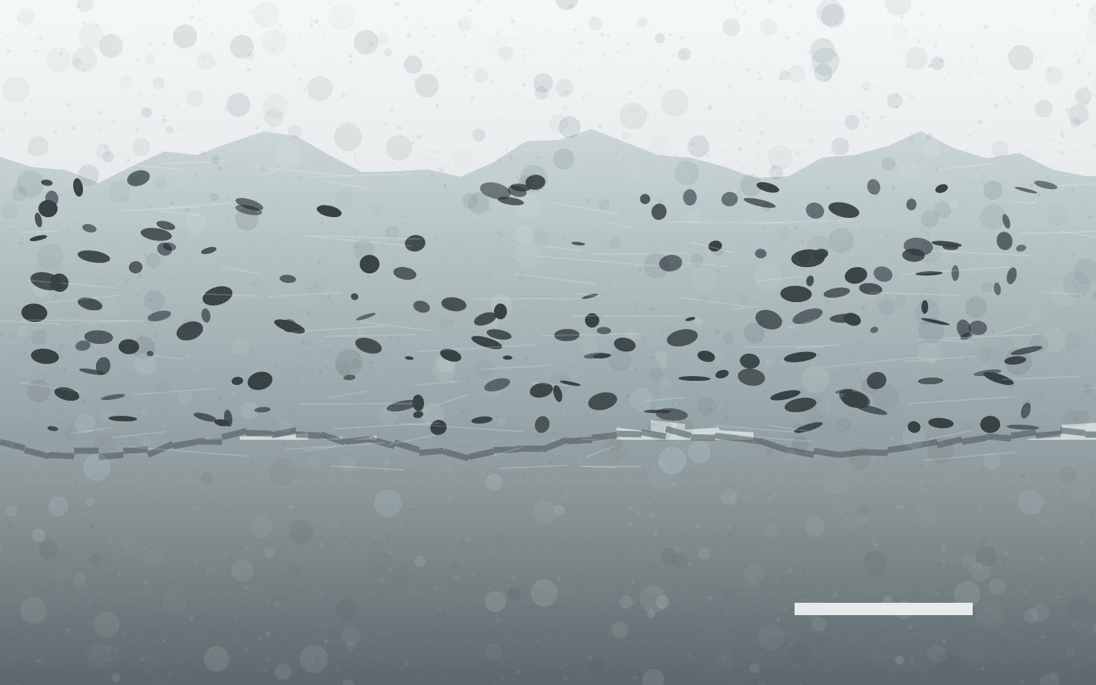
Measure layer thickness, porosity, pore size, coverage, and indentation dimensions from calibrated cross-section and surface images.
Available as a configurable Paint Measurement workflow in ConductImage.
 Representative input specimen
Start with the image
Provide a calibrated cross-section or surface image and the measurement question your team needs to answer.
One coating, four measurement questions
Keep the image, measurement, and review evidence together.
Choose the measurement that matches the specimen and the decision. These synthetic specimen visuals show the analysis intent; each result stays linked to its source image and overlay so your team can inspect how it was produced.
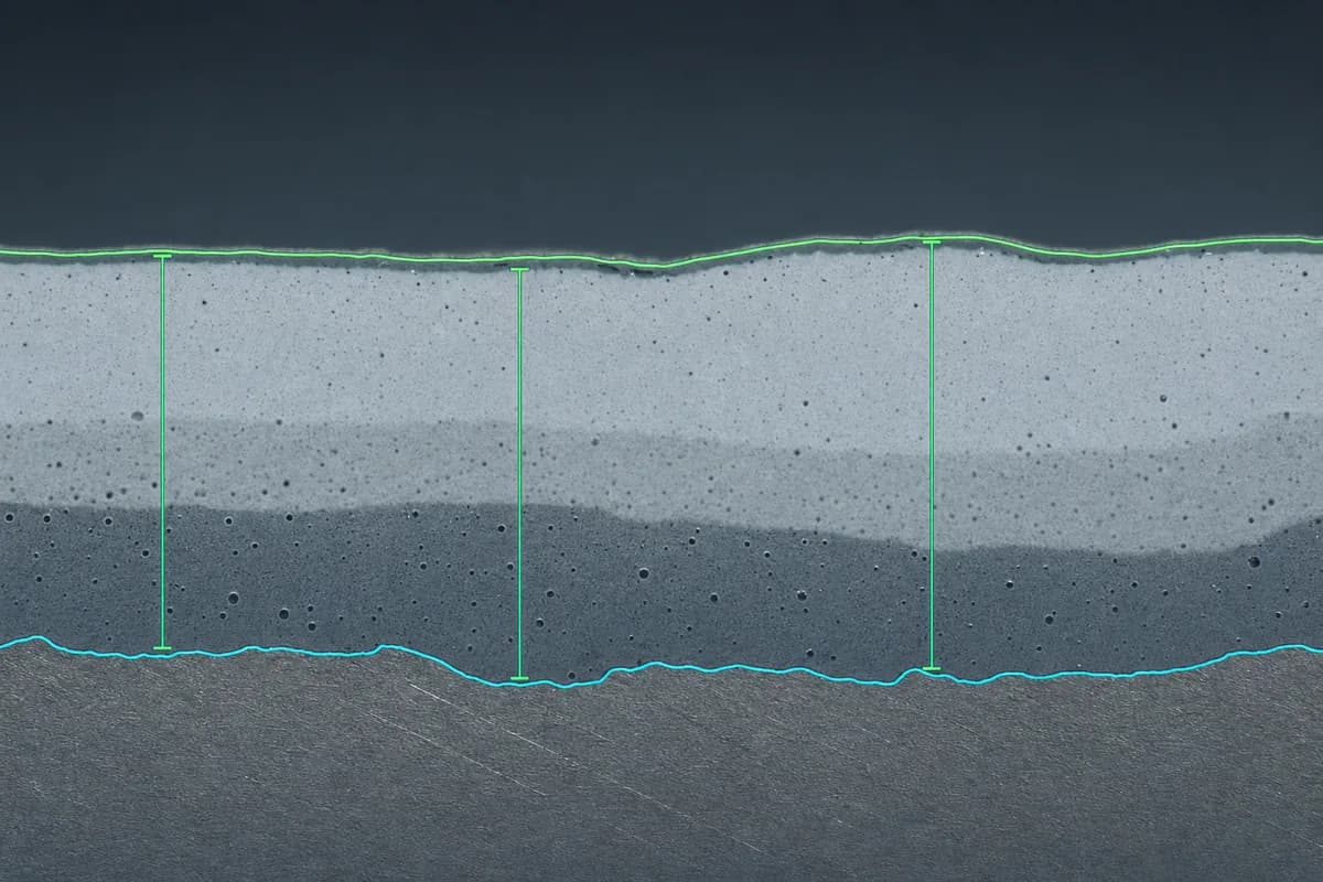
Layer thickness
Trace the upper and lower coating boundaries, then report each thickness point with mean, standard deviation, minimum, maximum, and percentiles.
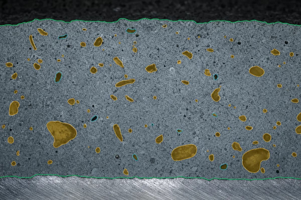
Porosity and pore size
Segment pores inside the eligible coating area, then report pore count, total pore area, porosity percentage, and size distribution.
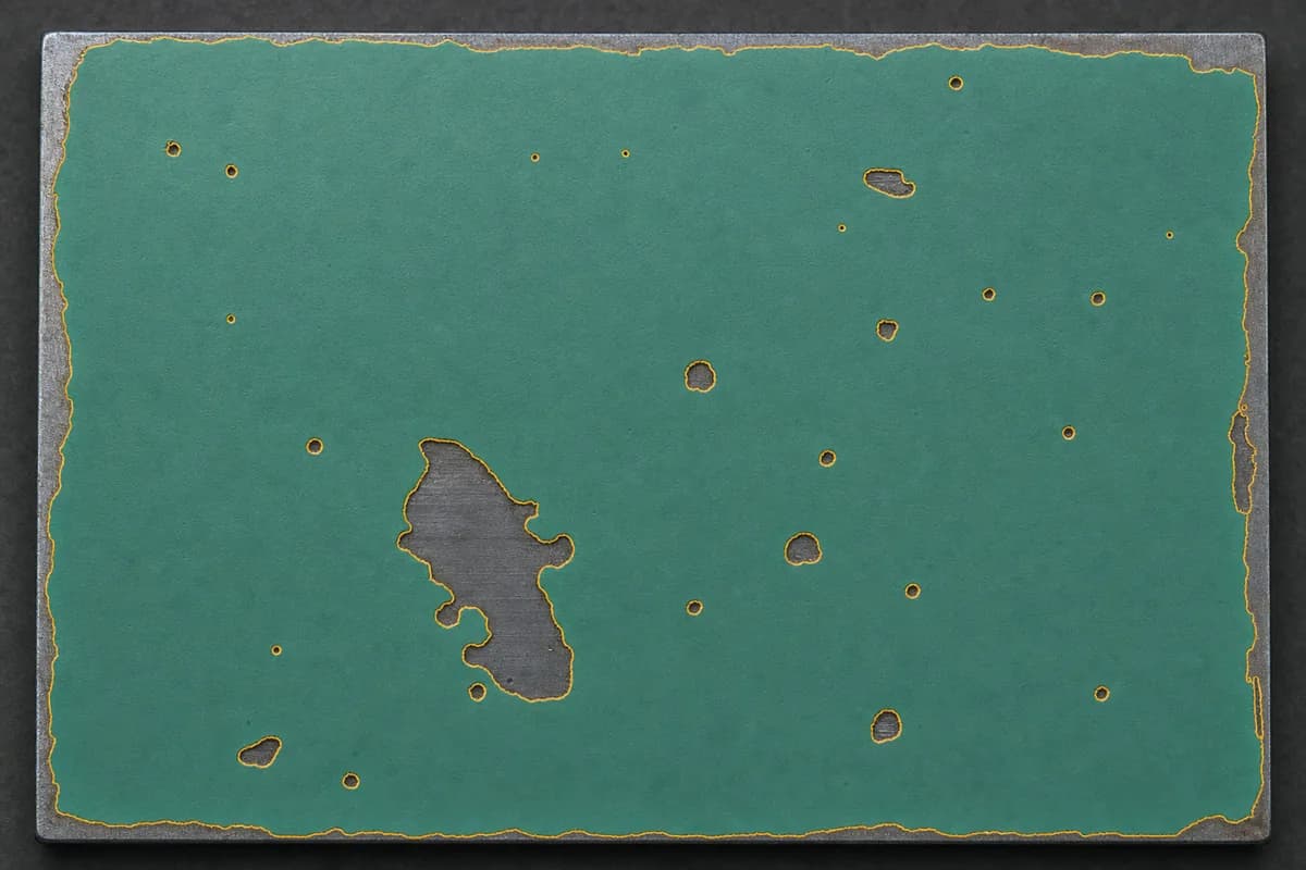
Coverage and holidays
Measure coated versus uncovered area on surface images and locate voids, holidays, or thin regions for review.
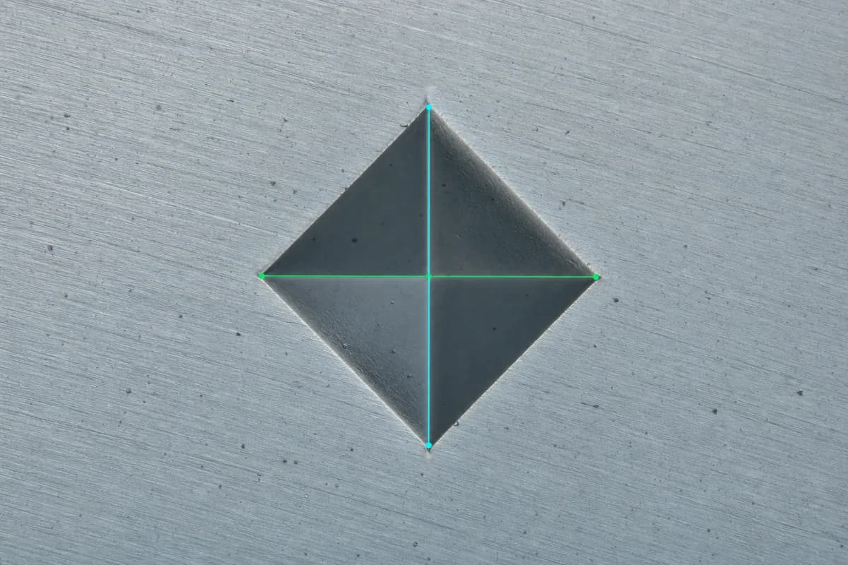
Indentation dimensions
Measure Vickers indentation diagonals and export dimensioned images when the image scale and test inputs are available.
See what the software returns
Move from a cross-section to reviewable evidence.
Explore the result views for thickness, porosity, and processed-image review. The examples use synthetic imagery and illustrative overlays, not customer data.
Paint Results
Explore illustrative ConductImage outputs
Each point records X position, upper bound Y0, lower bound Y1, and the resulting thickness.
Thickness distribution
Adjustable histogram bins
The fitted normal curve is shown only when the observed distribution is reasonably close to normal.
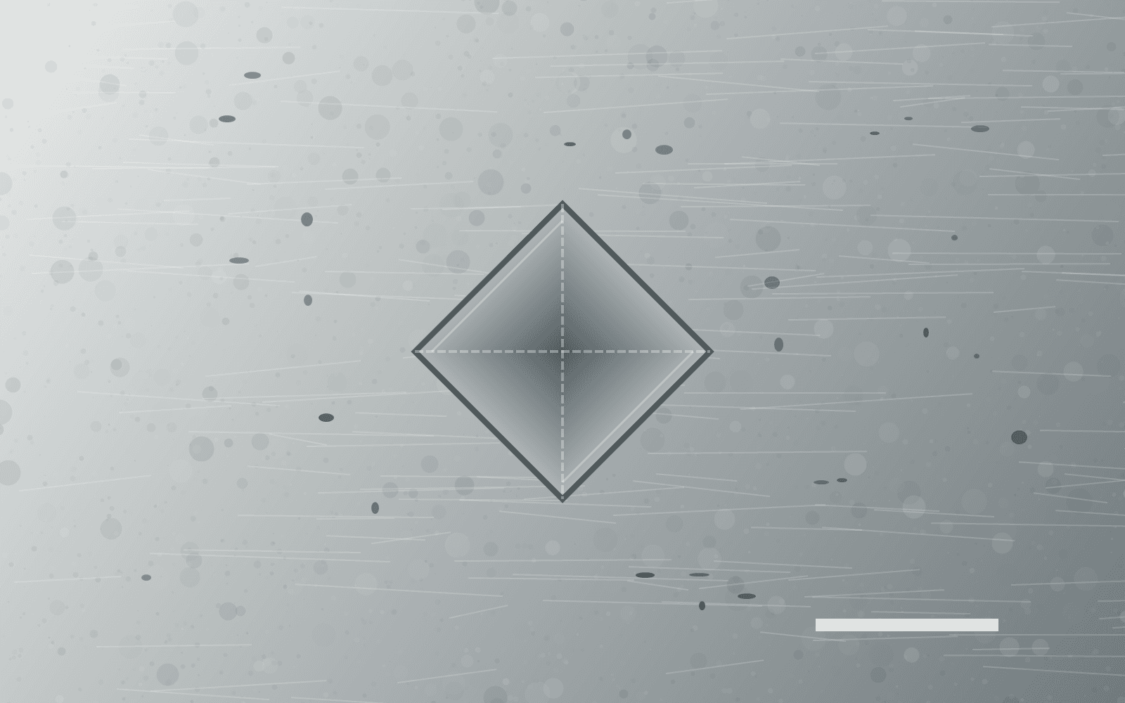
Supporting dimension workflow
Keep a dimensioned indentation image with the record.
Measure the horizontal and vertical Vickers diagonals from a calibrated image and retain the annotated frame for review or export.
This supports indentation dimensioning. A validated hardness calculation requires the applicable load, calibration, test method, and protocol validation.
The ConductImage workflow
Configure once. Review every image.
A protocol records the image source, selected model, calibration, and analysis settings. Run it on one image or a folder, then inspect the results before export.
- 1
Load and preview
Choose one image or a folder, preview the selection, and navigate the images in a batch.
- 2
Select the model and scale
Choose an available model, calibrate from a scale bar or known feature, and confirm the coating region.
- 3
Segment and review
Run the configured model, inspect the layer and pore overlays, and adjust the protocol when needed.
- 4
Compare and export
Review tables, distributions, source-result pairs, protocol settings, and annotated frames.
Complete software feature map
The documented Paint Measurement controls, in one place.
Image and folder intake
Open one image or an image folder, preview the selection, and move through every frame in the batch.
Model and protocol selection
Choose an available analysis model and retain the protocol parameters used for each calculation.
Point-level thickness
Inspect the X position, upper boundary Y0, lower boundary Y1, and calculated thickness at each point.
Porosity details
Review pore count, eligible ROI area, total pore area, porosity percentage, and pore-area details by image.
Synchronized image review
Filter ROI, porosity, or all results; pan, zoom, reset, and synchronize the source and processed views.
Distribution controls
Change histogram bin width and add a normal-curve overlay only when the observed distribution supports it.
Reported outputs
Statistics your team can trace back to the frame.
What to send
Start with representative images and a measurement goal.
- Representative images that include the coating and the boundaries you need to measure.
- A scale bar, pixel calibration, or known reference dimension when results need real units.
- The samples, lots, locations, or conditions that need to be compared.
- Your accepted manual or instrument method for validation and review.
Cross-section measurements describe the imaged plane. Bulk density, whole-part porosity, adhesion, and service life require their own reference tests.
Industrial applications
Built for coatings your lab already sections and photographs.
Automotive paint
Compare primer, basecoat, and clearcoat thickness with pore and coverage findings across panels or lots.
Thermal spray coatings
Measure layer thickness and pore area on polished cross-sections while keeping every result tied to its field.
Powder coatings
Review finished-layer uniformity, thin regions, pores, and surface coverage across representative images.
PCB conformal coatings
Locate uncovered areas and compare coating coverage around traces, pads, and component boundaries.
Related workflows
Coating thickness & porosity
Open the detailed cross-section workflow for calibrated thickness, pore masks, and Vickers images.
Open workflow →Coating & film coverage
Measure coverage, holidays, and uniformity from surface images.
Open workflow →Corrosion & pitting
Track corroded area, pits, and progression on coated or exposed surfaces.
Open workflow →Printed-part porosity
Classify gas pores and lack-of-fusion features in additive-manufactured parts.
Open workflow →Send a paint or coating image and a measurement goal
We will match it to the closest ConductVision workflow and identify what needs custom validation for your images.