Conduct Science is a premier manufacturer of research infrastructure, born from a mission to standardize the laboratory ecosystem. We combine industrial-grade precision with a scientist-led tech-transfer model, ensuring that every instrument we build solves a real-world experimental challenge. We replace "home-brew" setups with validated tools ranging from microsurgical suites to pathology systems. With a track record of >1,600 institutional partners and hundreds of citations, our equipment is engineered to minimize human error. We help you secure more data for less of your budget, delivering the reliability required for high-impact publication.


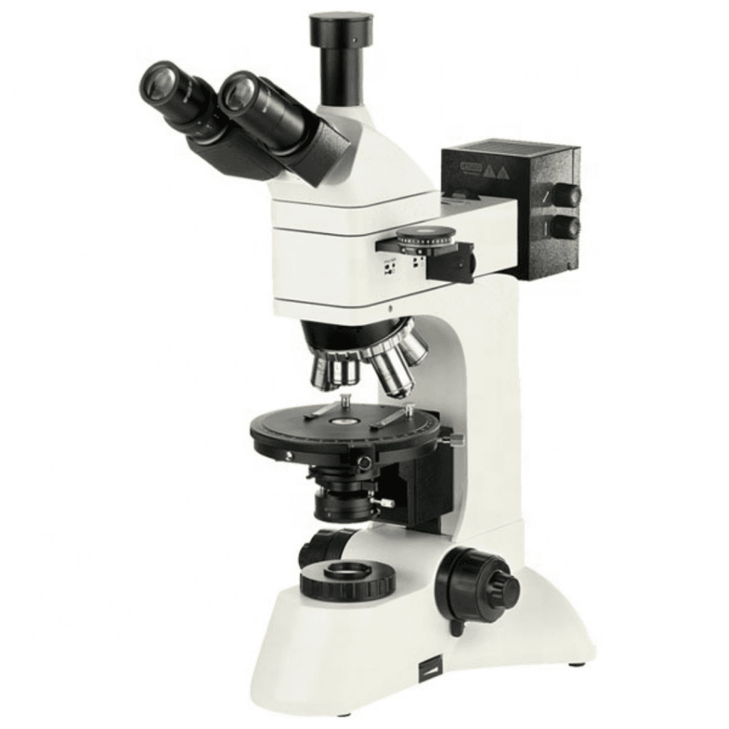
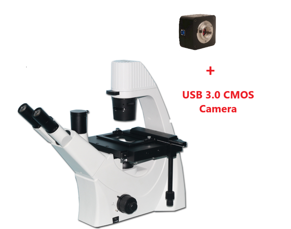
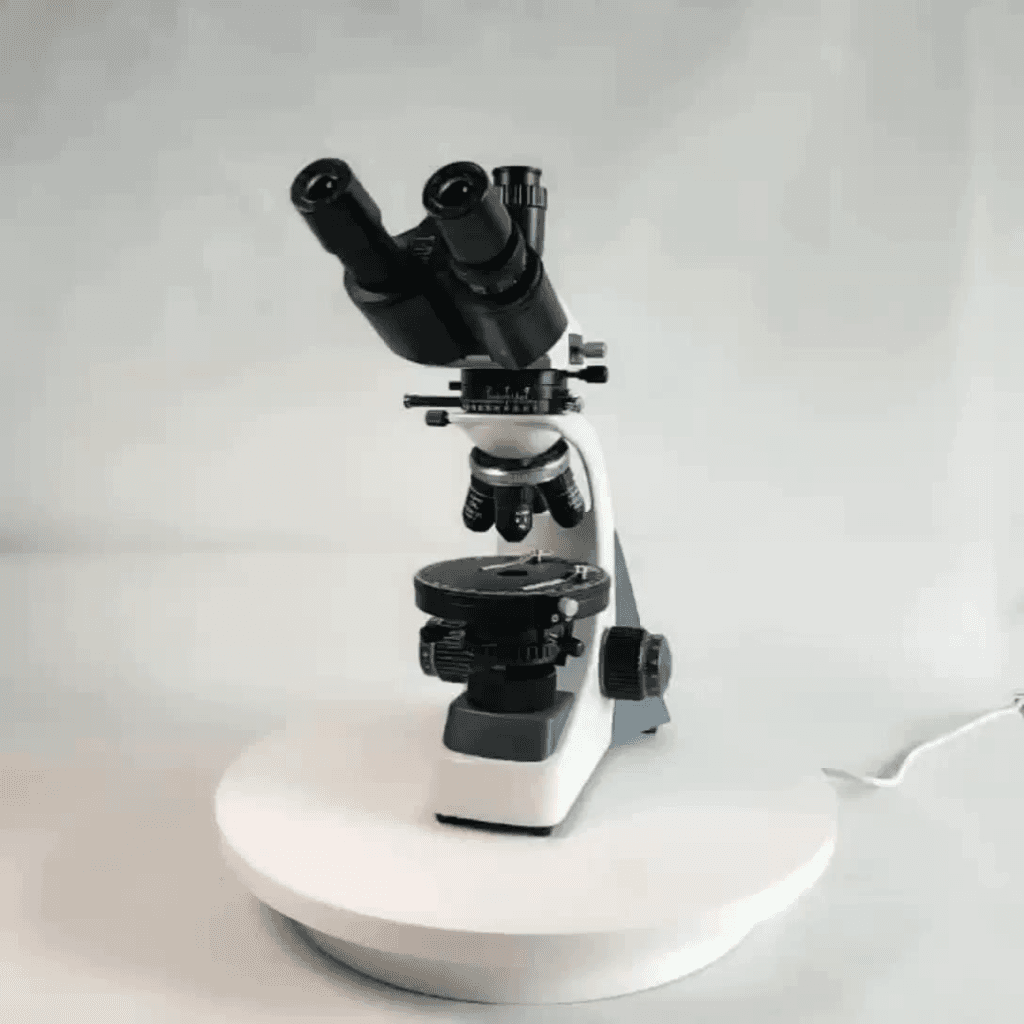


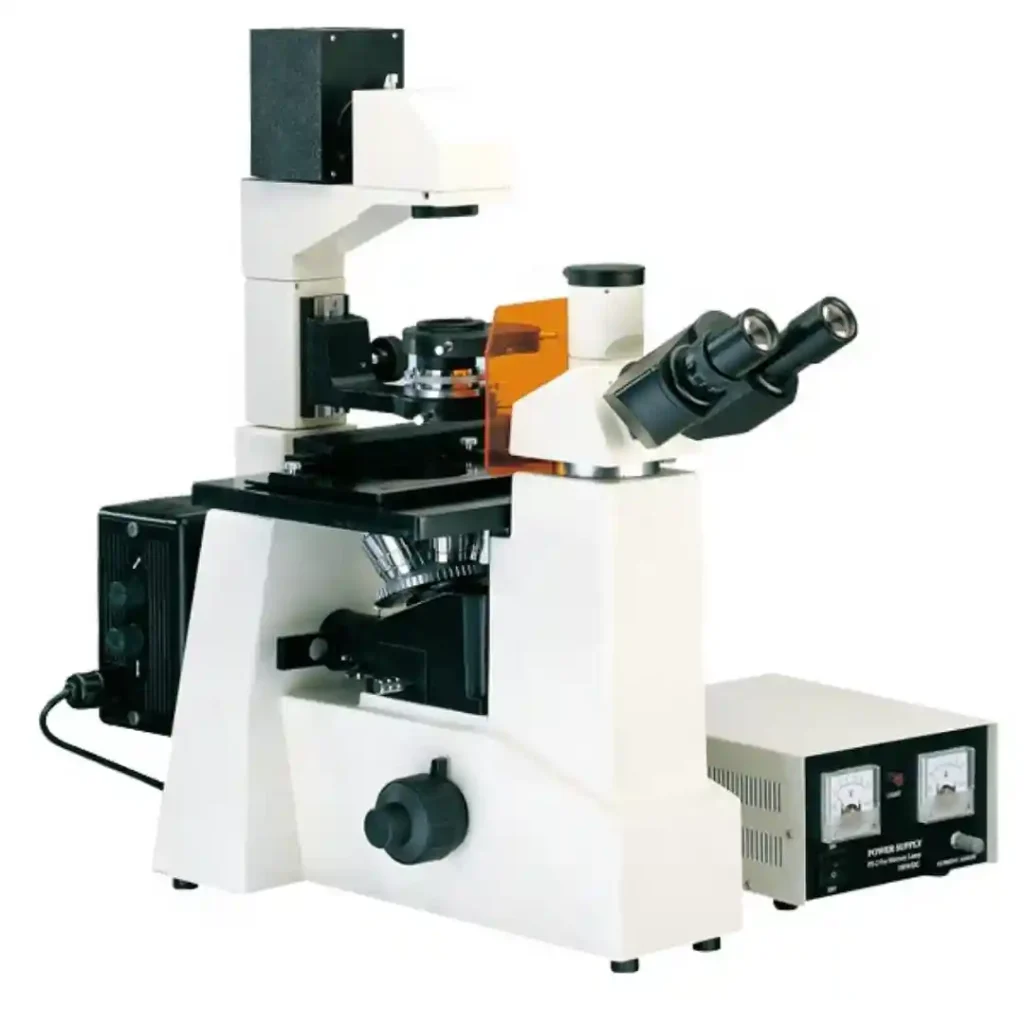


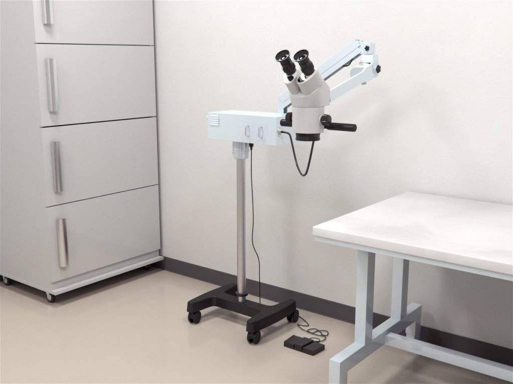


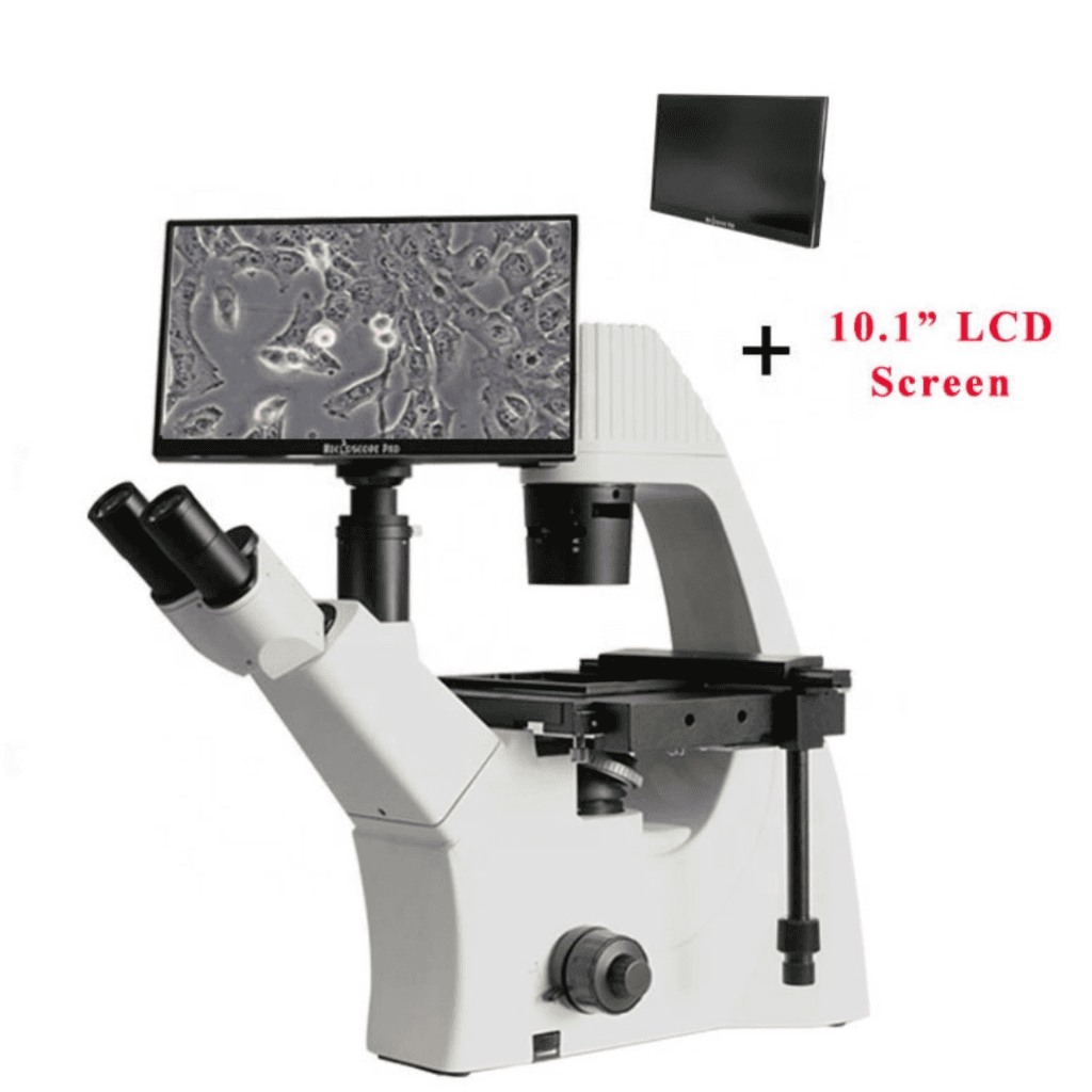

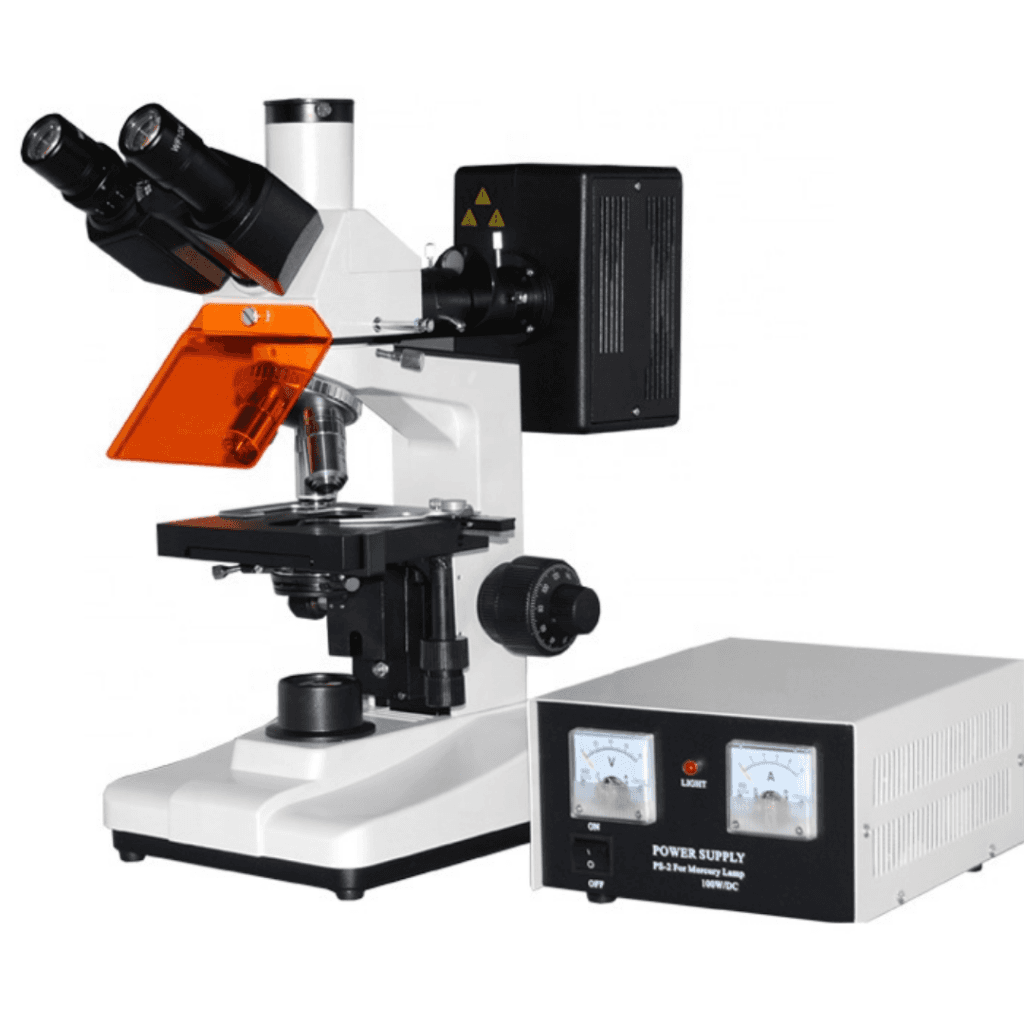

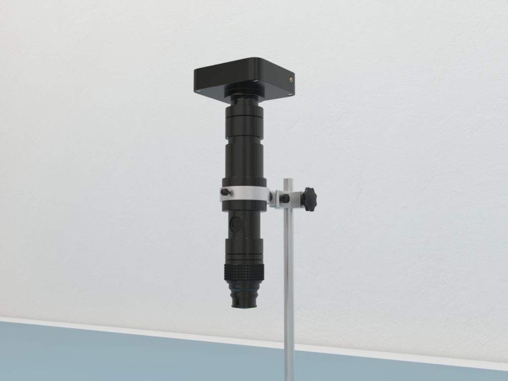


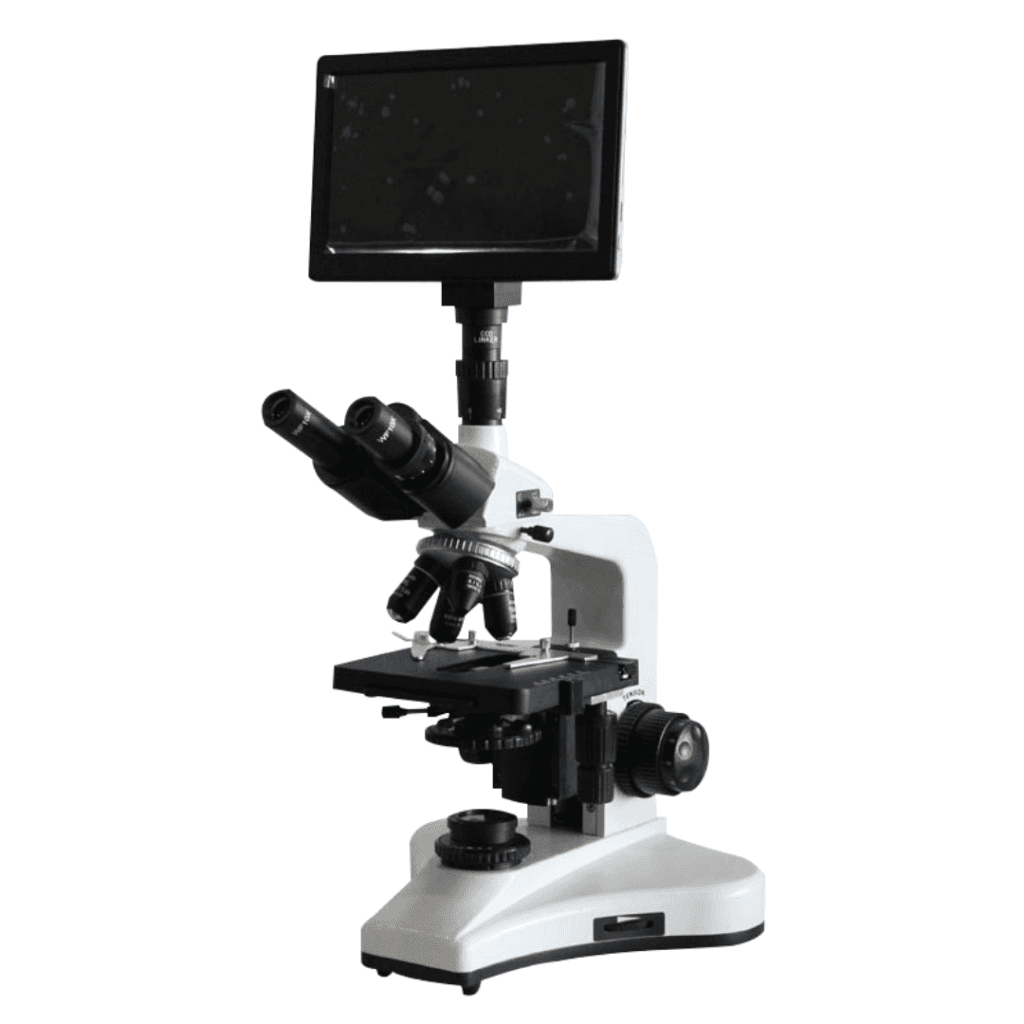
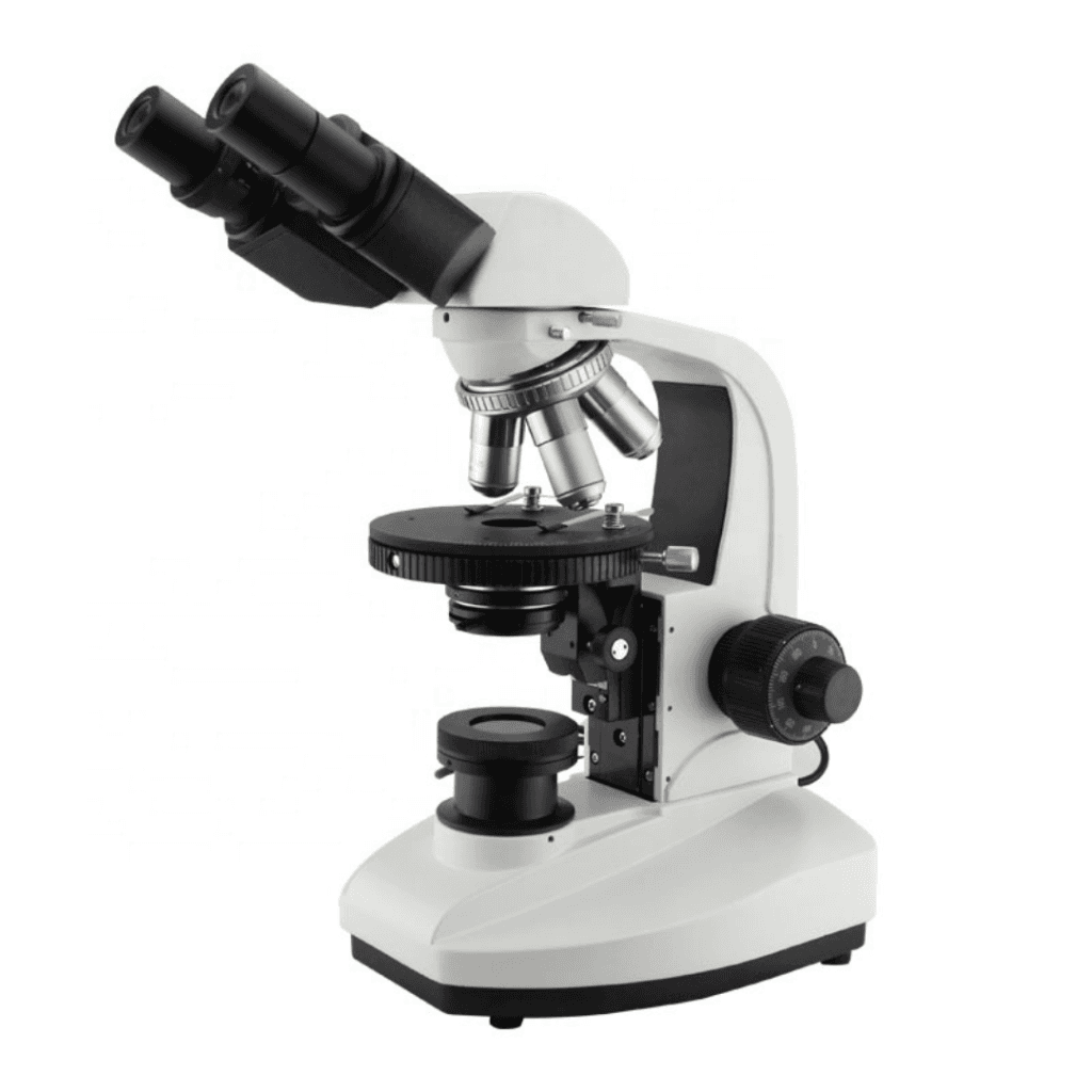
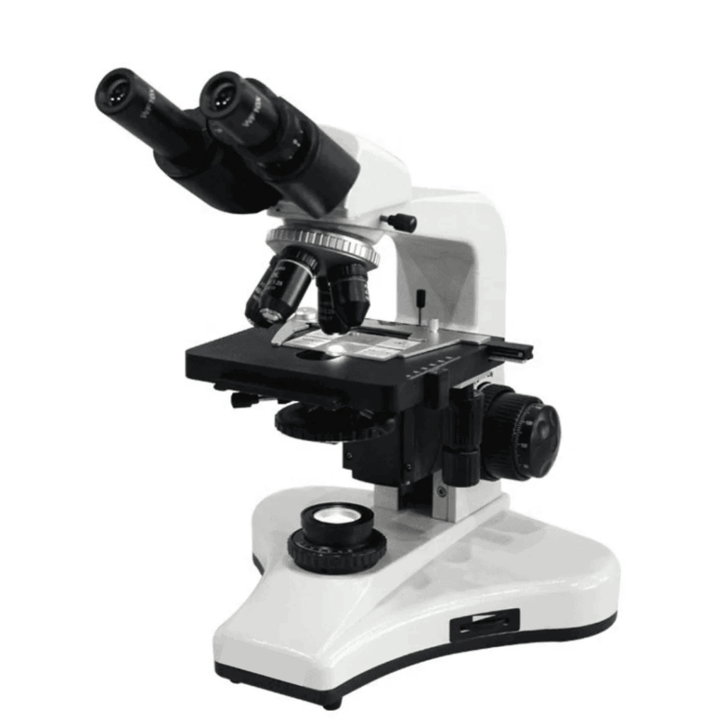
| Variables | Microscope, USb camera addon, Microscope + USb camera addon |
|---|---|
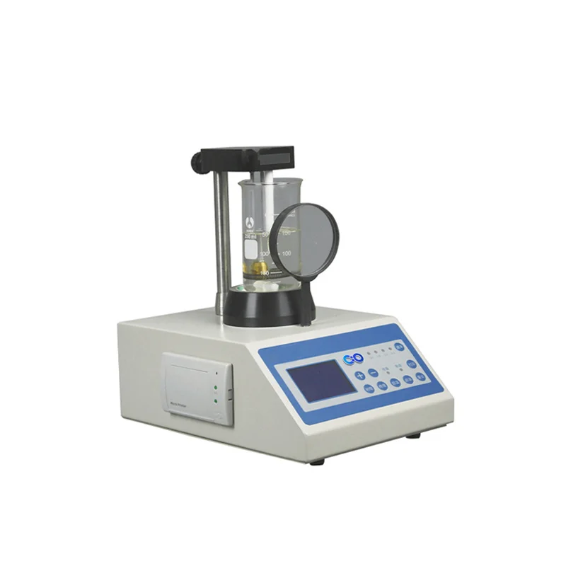
| Power/Voltage | 6V, 20W |
| Temperature Range | 5℃ to 35℃ |
| Accuracy | 2μm |
| operating_humidity | 20% to 80% @ 25℃ |
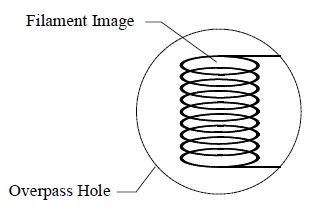
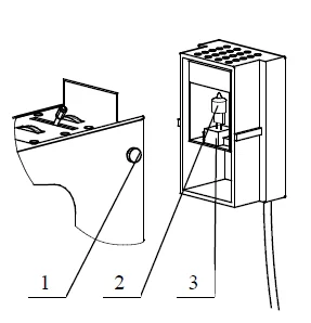
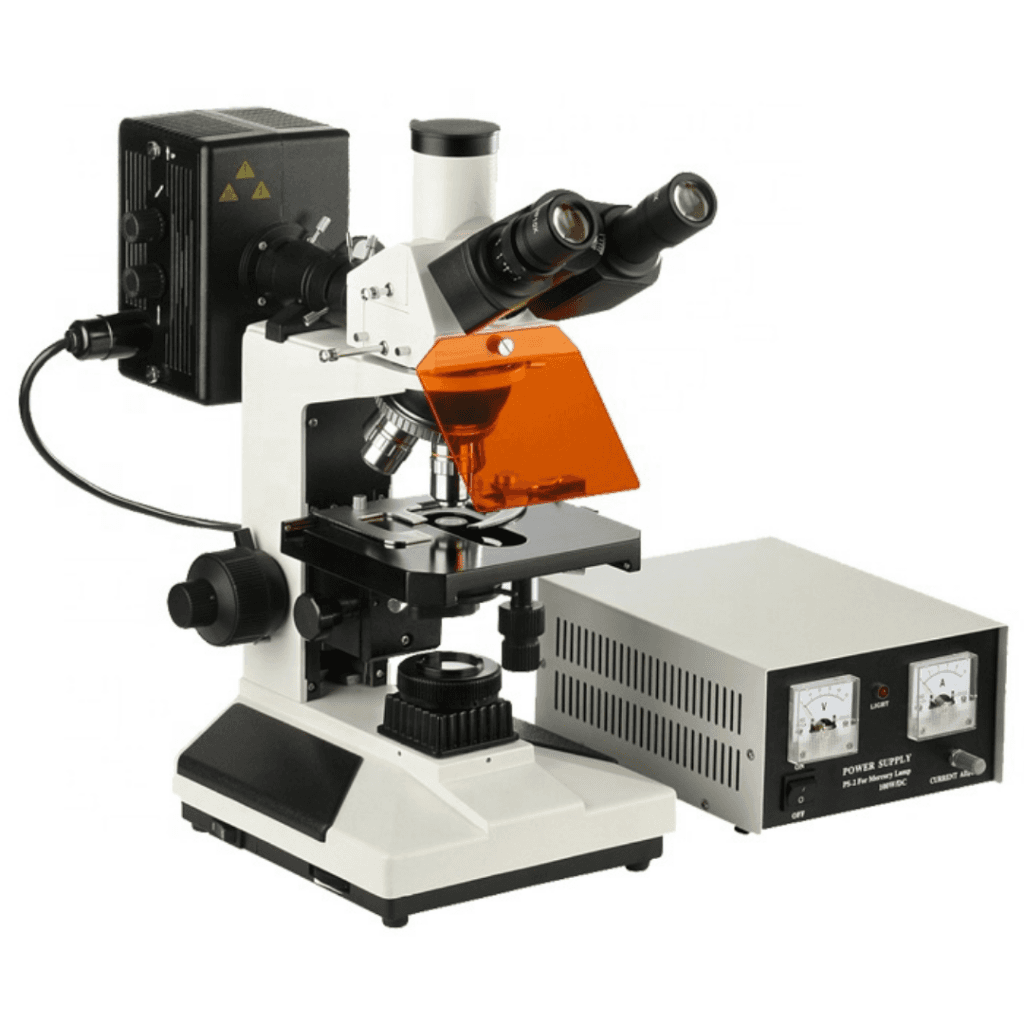
| lamp_type | Halogen |
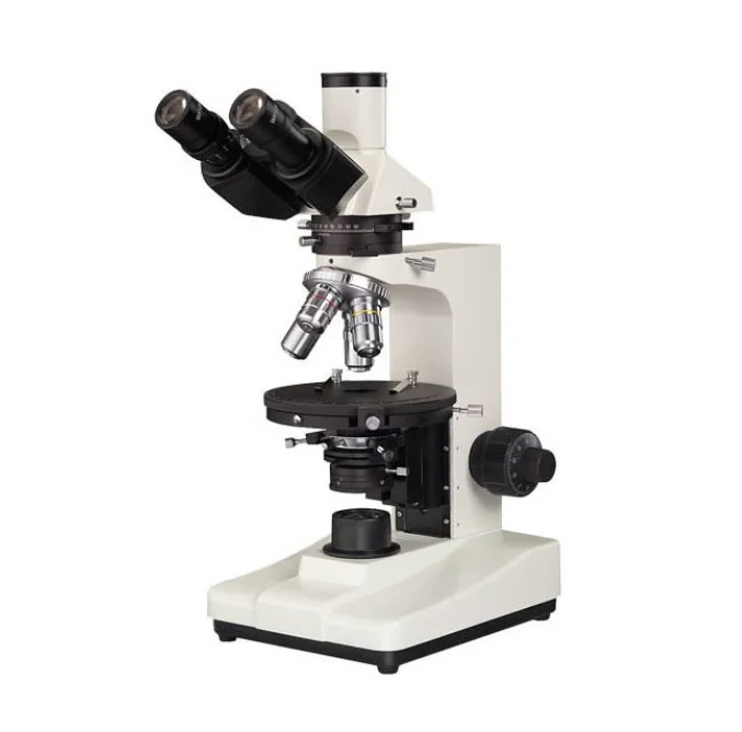
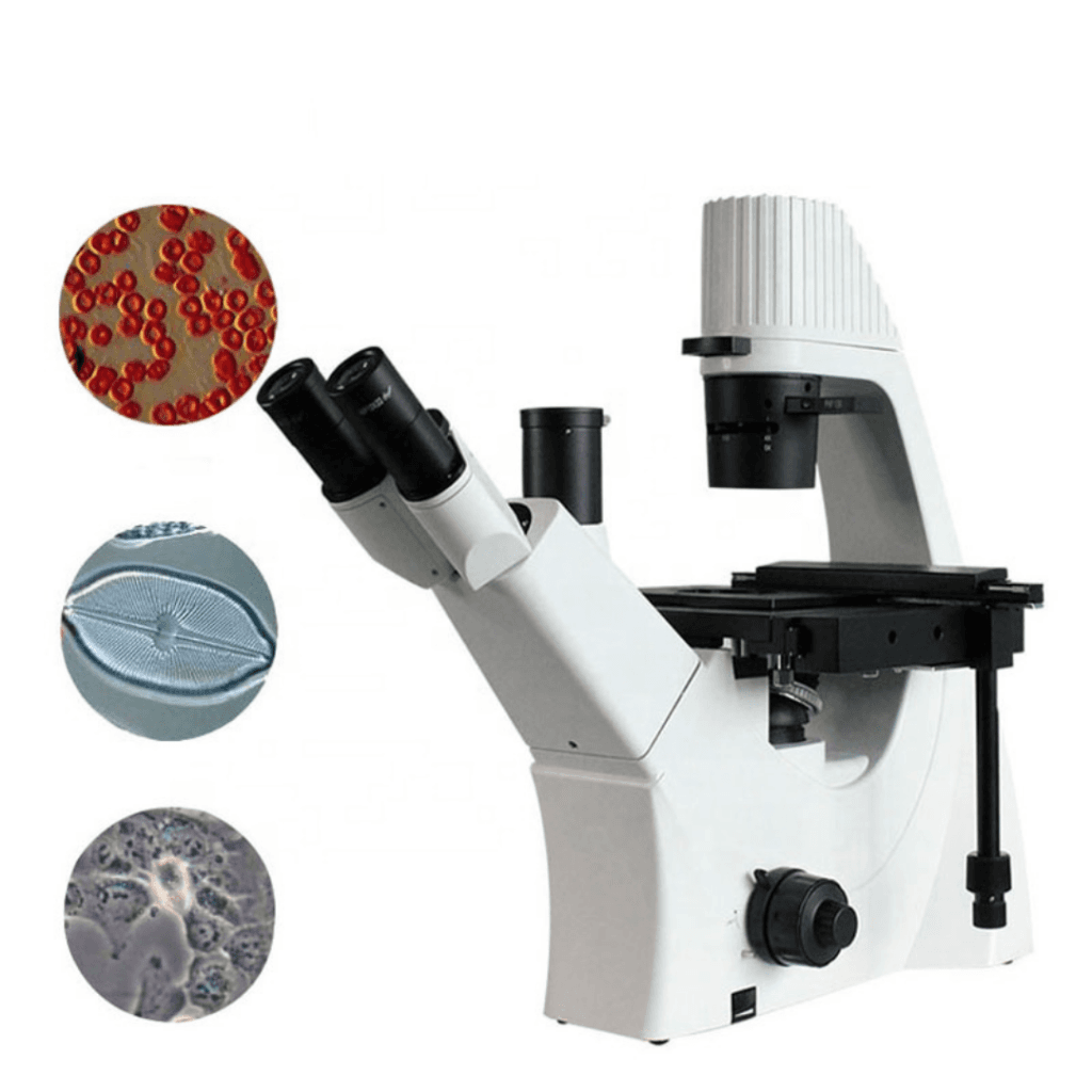
| eyepiece_magnification | 10X |
| eyepiece_field_diameter | 18mm |
| eyepiece_inclination | 30° |
| stage_diameter | 150mm |
| stage_rotation | 360° graduated in 1° increments |
| stage_vertical_movement | 30mm |
| minimum_retardation_resolution | 6' |
| fine_focusing_minimum_division | 2μm |
| polarizer_rotation | 360° rotatable with 0, 90, 180, 270 four scale |
| analyzer_rotation | 360° rotatable with scale and fine nonius |
| illumination_system | Transmitted illumination with 6V 20W halogen lamp |
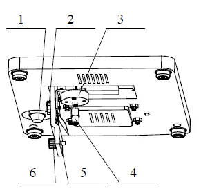
| brightness_control | Adjustable |
| trinocular_image_distribution | 100% of image light to top photography port |
| focus_system | Coaxial coarse/fine focus system with tensional adjustable and up stop |
| objectives | Strain-free plan achromatic objectives (center adjustable) |
| compensator_compatibility | λ compensator, λ/4 compensator or quartz wedge compensator |